Enable secure RS232 communication in industrial settings with ADM3252E and STM32F411RE
Isolated transceiver for secure data transfer

Published Oct 19, 2023
Click board™
RS232 Isolator Click
Dev. board
Fusion for ARM v8
Compiler
NECTO Studio
MCU
STM32F411RE
Your data's guardian, our fully isolated dual transceiver, is the ultimate bridge for secure UART to RS232 conversion, providing both security and reliability
A
A
Hardware Overview
How does it work?
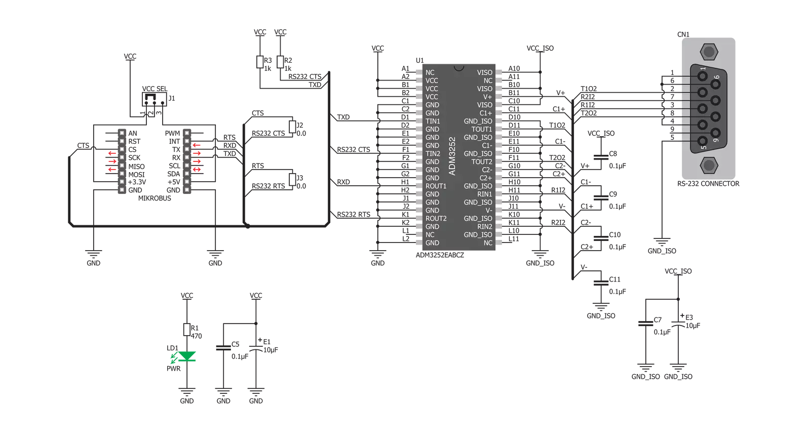
RS232 Isolator Click is based on the ADM3252E, an integrated dual-channel RS232 driver/receiver, with the iCoupler® isolation technology from Analog Devices. This integrated circuit features four integrated galvanic isolation elements that provide the required isolation level. RS232 level inputs are inverted and encoded into waveforms that are used to energize the primary windings of the integrated transformers. At the secondary windings, the induced waveforms are decoded back into the digital values and routed to the pins, with the appropriate TTL/CMOS voltage levels. The same working principle is applied in the opposite direction, too. This way, the digital signals are
effectively conducted through the isolation barrier. Besides the UART RX and TX lines, the click also supports the hardware flow control via the CTS and RTS lines. One of the two existing channels is used for the UART data communication itself, while the other channel is used for the hardware flow control lines. The usage of the control lines is not always mandatory, so the lines can be disconnected from the mikroBUS if needed, by unsoldering the SMD jumpers labeled as J1 and J2. The ADM3252E IC also features the isoPower™ technology - an integrated DC-DC converter for generating all the required voltage levels, making it possible to power the Click board™ by 3.3V or 5V.
The operating voltage for the Click board™ can be set with the onboard SMD jumper. RS232 Isolator click features the onboard D-Sub 9 (DE9) connector for an easy and secure connection. This Click board™ can operate with either 3.3V or 5V logic voltage levels selected via the VCC SEL jumper. This way, both 3.3V and 5V capable MCUs can use the communication lines properly. Also, this Click board™ comes equipped with a library containing easy-to-use functions and an example code that can be used as a reference for further development.


Features overview
Development board
Fusion for ARM v8 is a development board specially designed for the needs of rapid development of embedded applications. It supports a wide range of microcontrollers, such as different ARM® Cortex®-M based MCUs regardless of their number of pins, and a broad set of unique functions, such as the first-ever embedded debugger/programmer over WiFi. The development board is well organized and designed so that the end-user has all the necessary elements, such as switches, buttons, indicators, connectors, and others, in one place. Thanks to innovative manufacturing technology, Fusion for ARM v8 provides a fluid and immersive working experience, allowing access anywhere and under any
circumstances at any time. Each part of the Fusion for ARM v8 development board contains the components necessary for the most efficient operation of the same board. An advanced integrated CODEGRIP programmer/debugger module offers many valuable programming/debugging options, including support for JTAG, SWD, and SWO Trace (Single Wire Output)), and seamless integration with the Mikroe software environment. Besides, it also includes a clean and regulated power supply module for the development board. It can use a wide range of external power sources, including a battery, an external 12V power supply, and a power source via the USB Type-C (USB-C) connector.
Communication options such as USB-UART, USB HOST/DEVICE, CAN (on the MCU card, if supported), and Ethernet is also included. In addition, it also has the well-established mikroBUS™ standard, a standardized socket for the MCU card (SiBRAIN standard), and two display options for the TFT board line of products and character-based LCD. Fusion for ARM v8 is an integral part of the Mikroe ecosystem for rapid development. Natively supported by Mikroe software tools, it covers many aspects of prototyping and development thanks to a considerable number of different Click boards™ (over a thousand boards), the number of which is growing every day.

Microcontroller Overview
MCU Card / MCU
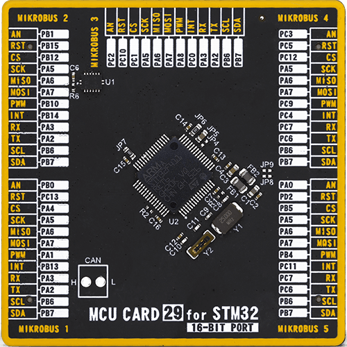
Type
8th Generation
Architecture
ARM Cortex-M4
MCU Memory (KB)
512
Silicon Vendor
STMicroelectronics
Pin count
64
RAM (Bytes)
131072
You complete me!
Accessories
DB9 Cable Female-to-Female (2m) cable is essential for establishing dependable serial data connections between devices. With its DB9 female connectors on both ends, this cable enables a seamless link between various equipment, such as computers, routers, switches, and other serial devices. Measuring 2 meters in length, it offers flexibility in arranging your setup without compromising data transmission quality. Crafted with precision, this cable ensures consistent and reliable data exchange, making it suitable for industrial applications, office environments, and home setups. Whether configuring networking equipment, accessing console ports, or utilizing serial peripherals, this cable's durable construction and robust connectors guarantee a stable connection. Simplify your data communication needs with the 2m DB9 female-to-female cable, an efficient solution designed to meet your serial connectivity requirements easily and efficiently.

Used MCU Pins
mikroBUS™ mapper
Take a closer look
Click board™ Schematic
Step by step
Project assembly

Start by selecting your development board and Click board™. Begin with the Fusion for ARM v8 as your development board.


Software Support
Library Description
This library contains API for RS232 Isolator Click driver.
Key functions:
rs232_2_set_rts- Function settings RTS staters232_2_get_cts- Read CTS staters232isolator_send_command- Function for send command
Open Source
Code example
The complete application code and a ready-to-use project are available through the NECTO Studio Package Manager for direct installation in the NECTO Studio. The application code can also be found on the MIKROE GitHub account.
/*!
 * \file
 * \brief Rs232Isolator Click example
 *
 * # Description
 * This example reads and processes data from RS232 Isolator Clicks.
 *
 * The demo application is composed of two sections :
 *
 * ## Application Init
 * Initializes driver.
 *
 * ## Application Task
 * Reads the received data.
 *
 * ## Additional Function
 * - rs232isolator_process ( ) - The general process of collecting presponce
 *                                   that sends a module.
 *
 * \author MikroE Team
 *
 */
// ------------------------------------------------------------------- INCLUDES

#include "board.h"
#include "log.h"
#include "rs232isolator.h"
#include "string.h"

#define PROCESS_COUNTER 10
#define PROCESS_RX_BUFFER_SIZE 500
#define PROCESS_PARSER_BUFFER_SIZE 500

#define TEXT_TO_SEND  "MikroE\r\n"

// ------------------------------------------------------------------ VARIABLES

#define DEMO_APP_RECEIVER
//#define DEMO_APP_TRANSMITER

static rs232isolator_t rs232isolator;
static log_t logger;

static char current_rsp_buf[ PROCESS_PARSER_BUFFER_SIZE ];
static uint8_t send_data_cnt = 0;
// ------------------------------------------------------- ADDITIONAL FUNCTIONS

static void rs232isolator_process ( void )
{
    int16_t rsp_size;
    uint16_t rsp_cnt = 0;

    char uart_rx_buffer[ PROCESS_RX_BUFFER_SIZE ] = { 0 };
    uint8_t check_buf_cnt;
    uint8_t process_cnt = PROCESS_COUNTER;

    // Clear parser buffer
    memset( current_rsp_buf, 0 , PROCESS_PARSER_BUFFER_SIZE );

    while( process_cnt != 0 )
    {
        rsp_size = rs232isolator_generic_read( &rs232isolator, &uart_rx_buffer, PROCESS_RX_BUFFER_SIZE );

        if ( rsp_size > 0 )
        {
            // Validation of the received data
            for ( check_buf_cnt = 0; check_buf_cnt < rsp_size; check_buf_cnt++ )
            {
                if ( uart_rx_buffer[ check_buf_cnt ] == 0 )
                {
                    uart_rx_buffer[ check_buf_cnt ] = 13;
                }
            }

            log_printf( &logger, "%s\r\n", uart_rx_buffer );

            // Storages data in parser buffer
            rsp_cnt += rsp_size;
            if ( rsp_cnt < PROCESS_PARSER_BUFFER_SIZE )
            {
                strncat( current_rsp_buf, uart_rx_buffer, rsp_size );
            }

            // Clear RX buffer
            memset( uart_rx_buffer, 0, PROCESS_RX_BUFFER_SIZE );
        }
        else
        {
            process_cnt--;

            // Process delay
            Delay_ms ( 100 );
        }
    }
    log_printf( &logger, "%s\r\n", current_rsp_buf );
}

// ------------------------------------------------------ APPLICATION FUNCTIONS

void application_init ( void )
{
    log_cfg_t log_cfg;
    rs232isolator_cfg_t cfg;

    /**
     * Logger initialization.
     * Default baud rate: 115200
     * Default log level: LOG_LEVEL_DEBUG
     * @note If USB_UART_RX and USB_UART_TX
     * are defined as HAL_PIN_NC, you will
     * need to define them manually for log to work.
     * See @b LOG_MAP_USB_UART macro definition for detailed explanation.
     */
    LOG_MAP_USB_UART( log_cfg );
    log_init( &logger, &log_cfg );
    log_info( &logger, "---- Application Init ----" );

    //  Click initialization.

    rs232isolator_cfg_setup( &cfg );
    RS232ISOLATOR_MAP_MIKROBUS( cfg, MIKROBUS_1 );
    rs232isolator_init( &rs232isolator, &cfg );
}

void application_task ( void )
{
#ifdef DEMO_APP_RECEIVER
    rs232isolator_process( );
#endif

#ifdef DEMO_APP_TRANSMITER
    rs232isolator_process( );

    if ( send_data_cnt == 5 )
    {
        rs232isolator_send_command( &rs232isolator, TEXT_TO_SEND );
        send_data_cnt = 0;
    }
    else
    {
        send_data_cnt++;
    }

#endif
}

int main ( void )
{
    /* Do not remove this line or clock might not be set correctly. */
    #ifdef PREINIT_SUPPORTED
    preinit();
    #endif

    application_init( );

    for ( ; ; )
    {
        application_task( );
    }

    return 0;
}

// ------------------------------------------------------------------------ END
Additional Support
Resources
Category:RS232


