Protect your signals while maintaining uninterrupted communication using ADM3260 and PIC32MX675F256L
Power and data protection in one elegant package!

Published Nov 02, 2023
Click board™
I2C Isolator 2 Click
Dev. board
Fusion for PIC v8
Compiler
NECTO Studio
MCU
PIC32MX675F256L
Redefine your I2C isolation experience with our hot-swappable isolator, where power and data protection merge seamlessly, simplifying your setup and enhancing system reliability.
A
A
Hardware Overview
How does it work?
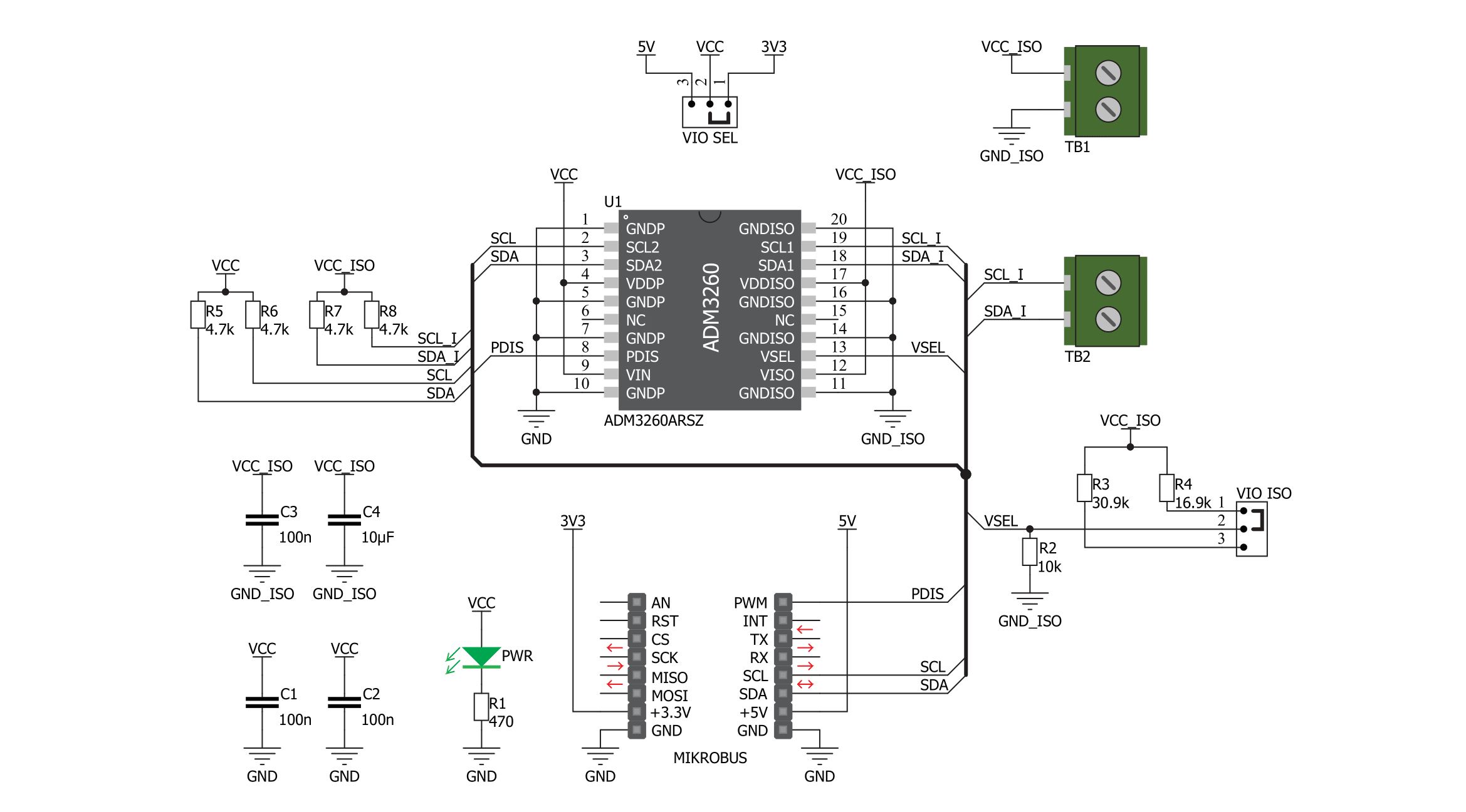
I2C Isolator 2 Click is based on the ADM3260, a hot-swappable dual I2C isolator with an integrated DC-to-DC converter from Analog Devices. The digital isolator block is on each side of a bidirectional I2C signal. Internally, the I2C interface is split into two unidirectional channels communicating in opposing directions via a dedicated iCoupler isolation channel for each. One channel senses the voltage state of one side and transmits its state to its respective second side.
This isolator can achieve I2C clock speeds of up to 1MHz and supports 3 - 5.5V logic levels. I2C Isolator 2 Click uses a standard 2-Wire I2C interface to allow isolated communication between the host MCU and the connected I2C device. The isolator allows you to disable the I2C communication over the PDIS pin, which, with a High logic level, puts the isolator in standby mode. The I2C Isolator 2 Click is equipped with the VIO ISO jumper, which allows you to work with isolated different logic
levels. The 3V3 is set by default. This Click board™ can operate with either 3.3V or 5V logic voltage levels selected via the VIO SEL jumper. This way, both 3.3V and 5V capable MCUs can use the communication lines properly. Also, this Click board™ comes equipped with a library containing easy-to-use functions and an example code that can be used as a reference for further development.


Features overview
Development board
Fusion for PIC v8 is a development board specially designed for the needs of rapid development of embedded applications. It supports a wide range of microcontrollers, such as different PIC, dsPIC, PIC24, and PIC32 MCUs regardless of their number of pins, and a broad set of unique functions, such as the first-ever embedded debugger/programmer over WiFi. The development board is well organized and designed so that the end-user has all the necessary elements, such as switches, buttons, indicators, connectors, and others, in one place. Thanks to innovative manufacturing technology, Fusion for PIC v8 provides a fluid and immersive working experience, allowing access anywhere and under any
circumstances at any time. Each part of the Fusion for PIC v8 development board contains the components necessary for the most efficient operation of the same board. In addition to the advanced integrated CODEGRIP programmer/debugger module, which offers many valuable programming/debugging options and seamless integration with the Mikroe software environment, the board also includes a clean and regulated power supply module for the development board. It can use a wide range of external power sources, including a battery, an external 12V power supply, and a power source via the USB Type-C (USB-C) connector. Communication options such as USB-UART, USB
HOST/DEVICE, CAN (on the MCU card, if supported), and Ethernet are also included, including the well-established mikroBUS™ standard, a standardized socket for the MCU card (SiBRAIN standard), and two display options (graphical and character-based LCD). Fusion for PIC v8 is an integral part of the Mikroe ecosystem for rapid development. Natively supported by Mikroe software tools, it covers many aspects of prototyping and development thanks to a considerable number of different Click boards™ (over a thousand boards), the number of which is growing every day.

Microcontroller Overview
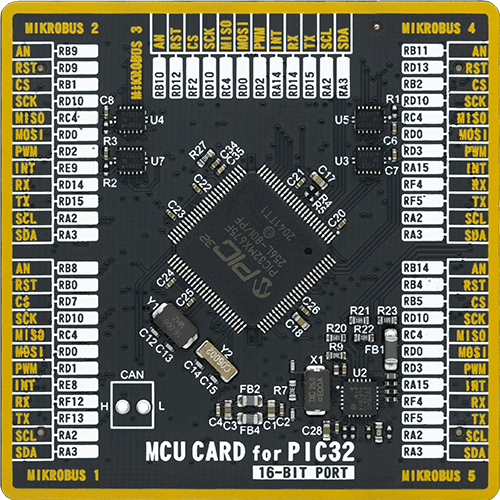
MCU Card / MCU
Type
8th Generation
Architecture
PIC32
MCU Memory (KB)
256
Silicon Vendor
Microchip
Pin count
100
RAM (Bytes)
65536
Used MCU Pins
mikroBUS™ mapper
Take a closer look
Click board™ Schematic
Step by step
Project assembly

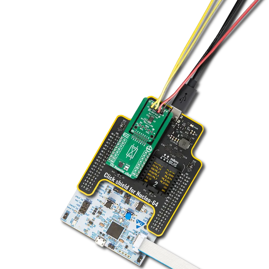
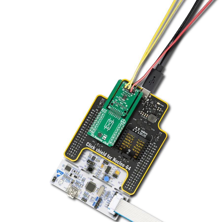
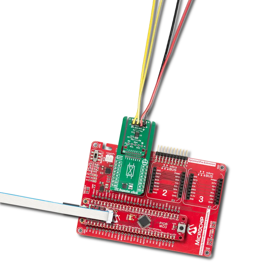
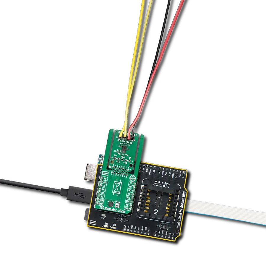
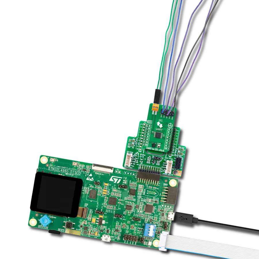
Start by selecting your development board and Click board™. Begin with the Fusion for PIC v8 as your development board.


Track your results in real time
Application Output
1. Application Output - In Debug mode, the 'Application Output' window enables real-time data monitoring, offering direct insight into execution results. Ensure proper data display by configuring the environment correctly using the provided tutorial.

2. UART Terminal - Use the UART Terminal to monitor data transmission via a USB to UART converter, allowing direct communication between the Click board™ and your development system. Configure the baud rate and other serial settings according to your project's requirements to ensure proper functionality. For step-by-step setup instructions, refer to the provided tutorial.

3. Plot Output - The Plot feature offers a powerful way to visualize real-time sensor data, enabling trend analysis, debugging, and comparison of multiple data points. To set it up correctly, follow the provided tutorial, which includes a step-by-step example of using the Plot feature to display Click board™ readings. To use the Plot feature in your code, use the function: plot(*insert_graph_name*, variable_name);. This is a general format, and it is up to the user to replace 'insert_graph_name' with the actual graph name and 'variable_name' with the parameter to be displayed.

Software Support
Library Description
This library contains API for I2C Isolator 2 Click driver.
Key functions:
i2cisolator2_write- This function writes a desired data to I2C bus.i2cisolator2_read- This function reads a desired number of data bytes from I2C bus.i2cisolator2_set_slave_address- This function sets the slave address.
Open Source
Code example
The complete application code and a ready-to-use project are available through the NECTO Studio Package Manager for direct installation in the NECTO Studio. The application code can also be found on the MIKROE GitHub account.
/*!
 * \file
 * \brief I2C Isolator 2 Click example
 *
 * # Description
 * This example showcases how to initialize, configure and use the I2C Isolator 2 Click module.
 * The Click provides I2C lines and power isolation for slave devices. In order for this
 * example to work, you need the EEPROM 3 Click.
 *
 * The demo application is composed of two sections :
 *
 * ## Application Init
 * Initializes the driver and enables the power output.
 *
 * ## Application Task
 * Writes the desired message to EEPROM 3 Click board and reads it back every 2 seconds.
 * All data is being displayed on the USB UART where you can track the program flow.
 *
 * @note
 * Make sure to provide the VCC power supply on VCC pin and EEPROM 3 Click.
 *
 * \author MikroE Team
 *
 */
// ------------------------------------------------------------------- INCLUDES

#include "board.h"
#include "log.h"
#include "i2cisolator2.h"

// ------------------------------------------------------------------ VARIABLES

#define EEPROM3_MEMORY_ADDRESS   0x10000ul
#define EEPROM3_SLAVE_ADDRESS    0x54
#define EEPROM3_DEMO_TEXT        "MikroE - I2C Isolator 2 with EEPROM 3 Click!"

static i2cisolator2_t i2cisolator2;
static log_t logger;

// ------------------------------------------------------ ADDITIONAL FUNCTIONS

err_t eeprom3_write_page( uint32_t address, uint8_t *data_in, uint8_t len )
{
    uint8_t data_buf[ 257 ] = { 0 };
    uint8_t slave_addr = ( uint8_t ) ( ( address >> 16 ) & 0x03 ) | EEPROM3_SLAVE_ADDRESS;
    i2cisolator2_set_slave_address ( &i2cisolator2, slave_addr );
    data_buf[ 0 ] = ( uint8_t ) ( ( address >> 8 ) & 0xFF );
    data_buf[ 1 ] = ( uint8_t ) ( address & 0xFF );
    for ( uint8_t cnt = 0; cnt < len; cnt++ )
    {
        data_buf[ cnt + 2 ] = data_in[ cnt ];
    }
    return i2cisolator2_write( &i2cisolator2, data_buf, len + 2 );
}

err_t eeprom3_read_page( uint32_t address, uint8_t *data_out, uint8_t len )
{
    uint8_t data_buf[ 2 ] = { 0 };
    uint8_t slave_addr = ( uint8_t ) ( ( address >> 16 ) & 0x03 ) | EEPROM3_SLAVE_ADDRESS;
    i2cisolator2_set_slave_address ( &i2cisolator2, slave_addr );
    data_buf[ 0 ] = ( uint8_t ) ( ( address >> 8 ) & 0xFF );
    data_buf[ 1 ] = ( uint8_t ) ( address & 0xFF );
    err_t error_flag = i2cisolator2_write( &i2cisolator2, data_buf, 2 );
    error_flag |= i2cisolator2_read( &i2cisolator2, data_out, len );
    return error_flag;
}
// ------------------------------------------------------ APPLICATION FUNCTIONS

void application_init ( )
{
    log_cfg_t log_cfg;
    i2cisolator2_cfg_t cfg;

    /**
     * Logger initialization.
     * Default baud rate: 115200
     * Default log level: LOG_LEVEL_DEBUG
     * @note If USB_UART_RX and USB_UART_TX
     * are defined as HAL_PIN_NC, you will
     * need to define them manually for log to work.
     * See @b LOG_MAP_USB_UART macro definition for detailed explanation.
     */
    LOG_MAP_USB_UART( log_cfg );
    log_init( &logger, &log_cfg );
    log_info( &logger, " Application Init " );

    // Click initialization.
    i2cisolator2_cfg_setup( &cfg );
    I2CISOLATOR2_MAP_MIKROBUS( cfg, MIKROBUS_1 );
    i2cisolator2_init( &i2cisolator2, &cfg );

    i2cisolator2_enable_power( &i2cisolator2, I2CISOLATOR2_POWER_ENABLE );
    Delay_ms ( 100 );

    log_info( &logger, " Application Task " );
}

void application_task ( )
{
    uint8_t read_buf[ 100 ] = { 0 };
    if ( I2CISOLATOR2_OK == eeprom3_write_page ( EEPROM3_MEMORY_ADDRESS, EEPROM3_DEMO_TEXT,
                                                 strlen( EEPROM3_DEMO_TEXT ) ) )
    {
        log_printf( &logger, " Demo text message is written to EEPROM 3 Click!\r\n" );
    }
    Delay_ms ( 1000 );

    if ( I2CISOLATOR2_OK == eeprom3_read_page ( EEPROM3_MEMORY_ADDRESS, read_buf,
                                                strlen( EEPROM3_DEMO_TEXT ) ) )
    {
        read_buf[ strlen( EEPROM3_DEMO_TEXT ) ] = 0;
        log_printf( &logger, " Read data: \"%s\"\r\n\n", read_buf );
    }
    Delay_ms ( 1000 );
}

int main ( void )
{
    /* Do not remove this line or clock might not be set correctly. */
    #ifdef PREINIT_SUPPORTED
    preinit();
    #endif

    application_init( );

    for ( ; ; )
    {
        application_task( );
    }

    return 0;
}

// ------------------------------------------------------------------------ END