Simplify color management and decision-making with APDS-9151 and TM4C1294NCPDT
The future of color analysis has arrived

Published Sep 24, 2023
Click board™
Color 14 Click
Dev. board
Fusion for Tiva v8
Compiler
NECTO Studio
MCU
TM4C1294NCPDT
Elevate your perception of the world around you through precise color sensing and analysis
A
A
Hardware Overview
How does it work?
Color 14 Click is based on the APDS-9151, a digital I2C compatible interface ambient light sensor (ALS), RGB, and proximity sensor with IR LED from Broadcom Limited. It uses four channels (Red, Green, Blue, and IR) in a specially designed matrix arrangement to achieve optimal angular response and accurate RGB spectral response with high lux accuracy over various light sources. It is suitable for use under a small aperture of the devices' cover windows, providing optimum viewing in diverse lighting conditions. The proximity detection feature operates well from bright sunlight to dark rooms. Proximity resolution can vary from 8bits to 11bits, with the measurement rate from 6.25ms to 400ms. To offset unwanted reflected light from the cover glass, a proximity detection (PS) intelligent cancellation level register allows an on-chip subtraction of the ADC count caused by the
unwanted reflected light from PS ADC output. Both the PS and ALS function independently provides maximum flexibility in application. The APDS-9151 has a wide dynamic range, with a programmable current in eight different steps and the LED modulation frequency, which can be set from 60kHz to 100kHz in five steps. Adding the micro-optic lenses within the module provides highly efficient transmission and reception of infrared energy, which lowers overall power dissipation. In addition, the device can be put into a low-power Standby mode, providing low average power consumption. Color 14 Click communicates with MCU using the standard I2C 2-Wire interface with a frequency of 100kHz in Standard and up to 400kHz in Fast Mode. Since the sensor is supplied with only a 3.3V logic voltage level, the Color 14 Click also features PCA9306 and SN74LVC1T45
voltage-level translators, allowing this Click board™ to be interfaced with both 3.3V and 5V MCUs. It also generates flexible ambient and proximity programmable interrupt signals routed on the INT pin of the mikroBUS™ socket, which is triggered if upper or lower threshold values are crossed. It is also possible to deactivate both sensors after a specific interrupt event occurs. This Click board™ can operate with either 3.3V or 5V logic voltage levels selected via the VIO SEL jumper. This way, both 3.3V and 5V capable MCUs can use the communication lines properly. Also, this Click board™ comes equipped with a library containing easy-to-use functions and an example code that can be used as a reference for further development.


Features overview
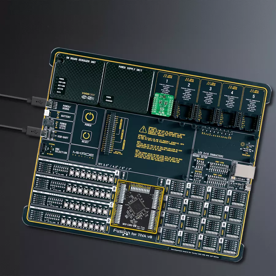
Development board
Fusion for TIVA v8 is a development board specially designed for the needs of rapid development of embedded applications. It supports a wide range of microcontrollers, such as different 32-bit ARM® Cortex®-M based MCUs from Texas Instruments, regardless of their number of pins, and a broad set of unique functions, such as the first-ever embedded debugger/programmer over a WiFi network. The development board is well organized and designed so that the end-user has all the necessary elements, such as switches, buttons, indicators, connectors, and others, in one place. Thanks to innovative manufacturing technology, Fusion for TIVA v8 provides a fluid and immersive working experience, allowing access
anywhere and under any circumstances at any time. Each part of the Fusion for TIVA v8 development board contains the components necessary for the most efficient operation of the same board. An advanced integrated CODEGRIP programmer/debugger module offers many valuable programming/debugging options, including support for JTAG, SWD, and SWO Trace (Single Wire Output)), and seamless integration with the Mikroe software environment. Besides, it also includes a clean and regulated power supply module for the development board. It can use a wide range of external power sources, including a battery, an external 12V power supply, and a power source via the USB Type-C (USB-C) connector.
Communication options such as USB-UART, USB HOST/DEVICE, CAN (on the MCU card, if supported), and Ethernet is also included. In addition, it also has the well-established mikroBUS™ standard, a standardized socket for the MCU card (SiBRAIN standard), and two display options for the TFT board line of products and character-based LCD. Fusion for TIVA v8 is an integral part of the Mikroe ecosystem for rapid development. Natively supported by Mikroe software tools, it covers many aspects of prototyping and development thanks to a considerable number of different Click boards™ (over a thousand boards), the number of which is growing every day.

Microcontroller Overview
MCU Card / MCU
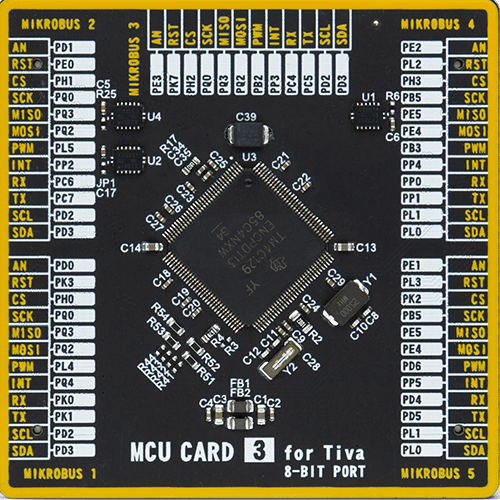
Type
8th Generation
Architecture
ARM Cortex-M4
MCU Memory (KB)
1024
Silicon Vendor
Texas Instruments
Pin count
128
RAM (Bytes)
262144
Used MCU Pins
mikroBUS™ mapper
Take a closer look
Click board™ Schematic

Step by step
Project assembly

Start by selecting your development board and Click board™. Begin with the Fusion for Tiva v8 as your development board.


Track your results in real time
Application Output
1. Application Output - In Debug mode, the 'Application Output' window enables real-time data monitoring, offering direct insight into execution results. Ensure proper data display by configuring the environment correctly using the provided tutorial.

2. UART Terminal - Use the UART Terminal to monitor data transmission via a USB to UART converter, allowing direct communication between the Click board™ and your development system. Configure the baud rate and other serial settings according to your project's requirements to ensure proper functionality. For step-by-step setup instructions, refer to the provided tutorial.

3. Plot Output - The Plot feature offers a powerful way to visualize real-time sensor data, enabling trend analysis, debugging, and comparison of multiple data points. To set it up correctly, follow the provided tutorial, which includes a step-by-step example of using the Plot feature to display Click board™ readings. To use the Plot feature in your code, use the function: plot(*insert_graph_name*, variable_name);. This is a general format, and it is up to the user to replace 'insert_graph_name' with the actual graph name and 'variable_name' with the parameter to be displayed.

Software Support
Library Description
This library contains API for Color 14 Click driver.
Key functions:
color14_get_rgb_ir- Read color data from devicecolor14_get_als- Read lux data from devicecolor14_get_proximity- Read proximity data from device
Open Source
Code example
The complete application code and a ready-to-use project are available through the NECTO Studio Package Manager for direct installation in the NECTO Studio. The application code can also be found on the MIKROE GitHub account.
/*!
 * @file main.c
 * @brief Color14 Click example
 *
 * # Description
 * This application showcases ability of Click board to read RGB and IR data
 * from device. Also it can be configured to read proximity data and
 * ALS data in lux units.
 *
 * The demo application is composed of two sections :
 *
 * ## Application Init
 * Initialization of host communication modules (UART, I2C) and additonal pin.
 * Read and check device ID, selects example and configures device for it.
 *
 * ## Application Task
 * Depending of selected example in task proximity and als data will be read from
 * device, or it will show ADC value for red, green, blue and ir data from device.
 *
 * ### Additioal function
 * static void color13_proximity_als_example ( void );
 * static void color13_rgb_example ( void );
 *
 * @author Luka Filipovic
 *
 */

#include "board.h"
#include "log.h"
#include "color14.h"

#define COLOR14_EXAMPLE_PS_LS   3
#define COLOR14_EXAMPLE_RGB     6

static color14_t color14;
static log_t logger;

static uint8_t example_type;

/**
 * @brief Proximity and Als data reading.
 * @details Example function for reading proximity and als data.
 * @return Nothing
 */
static void color14_proximity_als_example ( void );

/**
 * @brief RGB data reading.
 * @details Example function for reading rgb and ir data.
 * @return Nothing
 */
static void color14_rgb_example ( void );

void application_init ( void )
{
    log_cfg_t log_cfg;  /**< Logger config object. */
    color14_cfg_t color14_cfg;  /**< Click config object. */

    /**
     * Logger initialization.
     * Default baud rate: 115200
     * Default log level: LOG_LEVEL_DEBUG
     * @note If USB_UART_RX and USB_UART_TX
     * are defined as HAL_PIN_NC, you will
     * need to define them manually for log to work.
     * See @b LOG_MAP_USB_UART macro definition for detailed explanation.
     */
    LOG_MAP_USB_UART( log_cfg );
    log_init( &logger, &log_cfg );
    log_info( &logger, " Application Init " );

    // Click initialization.
    color14_cfg_setup( &color14_cfg );
    COLOR14_MAP_MIKROBUS( color14_cfg, MIKROBUS_1 );
    err_t init_flag = color14_init( &color14, &color14_cfg );
    if ( I2C_MASTER_ERROR == init_flag )
    {
        log_error( &logger, " Application Init Error. " );
        log_info( &logger, " Please, run program again... " );

        for ( ; ; );
    }

    uint8_t temp_data = 0;
    init_flag = color14_generic_read( &color14, COLOR14_REG_PART_ID, &temp_data, 1 );
    log_printf( &logger, " > ID: 0x%.2X\r\n", ( uint16_t )temp_data );

    if ( ( COLOR14_OK != init_flag ) && ( COLOR14_ID != temp_data ) )
    {
        log_error( &logger, " ID" );
        log_info( &logger, " Please, run program again... " );

        for ( ; ; );
    }

    //Select example
    example_type = COLOR14_EXAMPLE_RGB;
    color14_generic_write( &color14, COLOR14_REG_MAIN_CTRL, &example_type, 1 );

    if ( COLOR14_EXAMPLE_PS_LS == example_type )
    {
        //Configure proximity data to 11 bit
        color14_generic_read( &color14, COLOR14_REG_PS_MEASRATE, &temp_data, 1 );
        temp_data |= 0x18;
        color14_generic_write( &color14, COLOR14_REG_PS_MEASRATE, &temp_data, 1 );
    }

    Delay_ms ( 1000 );
    log_info( &logger, " Application Task " );
}

void application_task ( void )
{
    switch ( example_type )
    {
        case COLOR14_EXAMPLE_PS_LS:
        {
            color14_proximity_als_example( );
            break;
        }
        case COLOR14_EXAMPLE_RGB:
        {
            color14_rgb_example( );
            break;
        }
        default:
        {
            log_error( &logger, " Select example!" );
            break;
        }
    }
    Delay_ms ( 500 );
}

int main ( void )
{
    /* Do not remove this line or clock might not be set correctly. */
    #ifdef PREINIT_SUPPORTED
    preinit();
    #endif

    application_init( );

    for ( ; ; )
    {
        application_task( );
    }

    return 0;
}

static void color14_proximity_als_example ( void )
{
    //Proximity data
    uint16_t ps_data = 0;
    err_t error_flag = color14_get_proximity( &color14, &ps_data );
    log_printf( &logger, " > PS: %u\r\n", ps_data );
    if ( COLOR14_ERROR_OVF == error_flag )
    {
        log_error( &logger, " Overflow" );
    }
    //ALS data
    float lux = 0;
    color14_get_als( &color14, &lux );
    log_printf( &logger, " > LS[ lux ]: %.2f\r\n", lux );
    log_printf( &logger, "**********************************\r\n" );
}

static void color14_rgb_example ( void )
{
    color14_color_t color_data;

    color14_get_rgb_ir( &color14, &color_data );

    log_printf( &logger, " > R: %u\r\n", color_data.red );
    log_printf( &logger, " > G: %u\r\n", color_data.green );
    log_printf( &logger, " > B: %u\r\n", color_data.blue );
    log_printf( &logger, " > IR: %u\r\n", color_data.ir );
    log_printf( &logger, "**********************************\r\n" );
}

// ------------------------------------------------------------------------ END


