Improve performance of your BLDC motors with ATmega8A and STM32F765ZI
Revolutionize with precise motor control

Published Jul 26, 2023
Click board™
Brushless 6 Click
Dev. board
UNI-DS v8
Compiler
NECTO Studio
MCU
STM32F765ZI
Take control of your brushless motors with the most incredible accuracy. Unleash the power of PWM for optimal BLDC management!
A
A
Hardware Overview
How does it work?
Brushless 6 Click is based on the ATmega8A MCU from Microchip. It uses a 50Hz PWM signal at one of the input pins, routed to the PWM pin of the mikroBUS™ socket. The duty cycle of the incoming PWM signal is decoded by the onboard ATmega8A MCU so that a certain pulse width range is used to set the speed and direction of the rotation. The MikroElektronika demo application,
provided with the Brushless 6 Click, uses simplified functions to calibrate and set the speed and direction of the BLDC motor to be used as a reference for future design. Since the MCU output can't be used to drive heavier loads directly, the stator coils are driven through the MOSFET transistors network, controlled by the MCU. The electrical circuit that powers the coils is also
known as the "invertor" circuit because it provides both positive and negative voltages from the connected external power supply. The motor can be connected via the onboard connector, which provides an easy and secure connection. A power connector is also used to connect the external power supply, up to 12V.

Features overview
Development board
UNI-DS v8 is a development board specially designed for the needs of rapid development of embedded applications. It supports a wide range of microcontrollers, such as different STM32, Kinetis, TIVA, CEC, MSP, PIC, dsPIC, PIC32, and AVR MCUs regardless of their number of pins, and a broad set of unique functions, such as the first-ever embedded debugger/programmer over WiFi. The development board is well organized and designed so that the end-user has all the necessary elements, such as switches, buttons, indicators, connectors, and others, in one place. Thanks to innovative manufacturing technology, UNI-DS v8 provides a fluid and immersive working experience, allowing access anywhere and under any
circumstances at any time. Each part of the UNI-DS v8 development board contains the components necessary for the most efficient operation of the same board. An advanced integrated CODEGRIP programmer/debugger module offers many valuable programming/debugging options, including support for JTAG, SWD, and SWO Trace (Single Wire Output)), and seamless integration with the Mikroe software environment. Besides, it also includes a clean and regulated power supply module for the development board. It can use a wide range of external power sources, including a battery, an external 12V power supply, and a power source via the USB Type-C (USB-C) connector. Communication options such as USB-UART, USB
HOST/DEVICE, CAN (on the MCU card, if supported), and Ethernet is also included. In addition, it also has the well-established mikroBUS™ standard, a standardized socket for the MCU card (SiBRAIN standard), and two display options for the TFT board line of products and character-based LCD. UNI-DS v8 is an integral part of the Mikroe ecosystem for rapid development. Natively supported by Mikroe software tools, it covers many aspects of prototyping and development thanks to a considerable number of different Click boards™ (over a thousand boards), the number of which is growing every day.

Microcontroller Overview
MCU Card / MCU
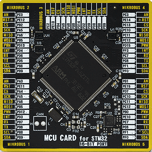
Type
8th Generation
Architecture
ARM Cortex-M7
MCU Memory (KB)
2048
Silicon Vendor
STMicroelectronics
Pin count
144
RAM (Bytes)
524288
You complete me!
Accessories
Brushless DC (BLDC) Motor with a Hall sensor represents a high-performance motor from the 42BLF motor series. This motor, wired in a star configuration, boasts a Hall Effect angle of 120°, ensuring precise and reliable performance. With a compact motor length of 47mm and a lightweight design tipping the scales at just 0.29kg, this BLDC motor is engineered to meet your needs. Operating flawlessly at a voltage rating of 24VDC and a speed range of 4000 ± 10% RPM, this motor offers consistent and dependable power. It excels in a normal operational temperature range from -20 to +50°C, maintaining efficiency with a rated current of 1.9A. Also, this product seamlessly integrates with all Brushless Click boards™ and those that require BLDC motors with Hall sensors.

Used MCU Pins
mikroBUS™ mapper
Take a closer look
Click board™ Schematic

Step by step
Project assembly

Start by selecting your development board and Click board™. Begin with the UNI-DS v8 as your development board.


Software Support
Library Description
This library contains API for Brushless 6 Click driver.
Key functions:
brushless6_pwm_start- Start PWM modulebrushless6_pwm_stop- Stop PWM modulebrushless6_set_duty_cycle- Generic sets PWM duty cycle
Open Source
Code example
The complete application code and a ready-to-use project are available through the NECTO Studio Package Manager for direct installation in the NECTO Studio. The application code can also be found on the MIKROE GitHub account.
/*!
 * \file
 * \brief Brushless6 Click example
 *
 * # Description
 * Brushless 6 Click is designed to drive a three-phase sensorless.
 *
 * The demo application is composed of two sections :
 *
 * ## Application Init
 * This function initializes and configures the logger and the Click board.
 *
 * ## Application Task
 * This function drives the motor in both directions increasing and decreasing the speed of the motor.
 *
 * ## NOTE
 * The maximal PWM Clock frequency for this Click board is 500 Hz.
 * So, the user will need to decrease the MCU's main clock frequency in MCU Settings in order to get up-to 500 Hz PWM clock frequency.
 *
 *
 * \author MikroE Team
 *
 */
// ------------------------------------------------------------------- INCLUDES

#include "board.h"
#include "log.h"
#include "brushless6.h"

// ------------------------------------------------------------------ VARIABLES

static brushless6_t brushless6;
static log_t logger;

static float duty_cycle;

// ------------------------------------------------------- ADDITIONAL FUNCTIONS

void brushless6_calibration( )
{
    brushless6_pwm_start( &brushless6 );

    brushless6_set_duty_cycle( &brushless6, BRUSHLESS6_MIN_PWM_DC );
    Delay_1sec( );
    Delay_1sec( );
}

void brushless6_setings( )
{
    brushless6_set_duty_cycle( &brushless6, BRUSHLESS6_INIT_DC );
    Delay_1sec( );
    Delay_1sec( );
}

static void clockwise ( )
{
    log_printf( &logger, "\r\n------------------------------\r\n" );
    log_printf( &logger, " * Clockwise *\r\n" );
    Delay_1sec( );

    for( duty_cycle = BRUSHLESS6_INIT_DC; duty_cycle > BRUSHLESS6_1MS_DC; duty_cycle -= BRUSHLESS6_PERIOD )
    {
        brushless6_set_duty_cycle( &brushless6, duty_cycle );
        log_printf( &logger, "  > " );
        Delay_1sec( );
    }

    log_printf( &logger, "\r\n" );

    for( duty_cycle = BRUSHLESS6_1MS_DC; duty_cycle < BRUSHLESS6_INIT_DC; duty_cycle += BRUSHLESS6_PERIOD )
    {
        brushless6_set_duty_cycle( &brushless6, duty_cycle );
        log_printf( &logger, "  < " );
        Delay_1sec( );
    }
}

static void counter_clockwise ( )
{
    log_printf( &logger, "\r\n------------------------------\r\n" );
    log_printf( &logger, " * Counter clockwise *\r\n" );
    Delay_1sec( );

    for( duty_cycle = BRUSHLESS6_INIT_DC; duty_cycle < BRUSHLESS6_2MS_DC - BRUSHLESS6_PERIOD; duty_cycle += BRUSHLESS6_PERIOD )
    {
        brushless6_set_duty_cycle( &brushless6, duty_cycle );
        log_printf( &logger, "  > " );
        Delay_1sec( );
    }
    log_printf( &logger, "\r\n" );

    for( duty_cycle = BRUSHLESS6_2MS_DC - BRUSHLESS6_PERIOD; duty_cycle > BRUSHLESS6_INIT_DC; duty_cycle -= BRUSHLESS6_PERIOD )
    {
        brushless6_set_duty_cycle( &brushless6, duty_cycle );
        log_printf( &logger, "  < " );
        Delay_1sec( );
    }
}

// ------------------------------------------------------ APPLICATION FUNCTIONS

void application_init ( void )
{
    log_cfg_t log_cfg;
    brushless6_cfg_t cfg;

    /**
     * Logger initialization.
     * Default baud rate: 115200
     * Default log level: LOG_LEVEL_DEBUG
     * @note If USB_UART_RX and USB_UART_TX
     * are defined as HAL_PIN_NC, you will
     * need to define them manually for log to work.
     * See @b LOG_MAP_USB_UART macro definition for detailed explanation.
     */
    LOG_MAP_USB_UART( log_cfg );
    log_init( &logger, &log_cfg );
    log_info( &logger, "---- Application Init ----" );

    //  Click initialization.

    brushless6_cfg_setup( &cfg );
    BRUSHLESS6_MAP_MIKROBUS( cfg, MIKROBUS_1 );
    brushless6_init( &brushless6, &cfg );
    brushless6_calibration( );
    brushless6_setings( );
}

void application_task ( void )
{
    clockwise( );
    counter_clockwise( );
}

int main ( void )
{
    /* Do not remove this line or clock might not be set correctly. */
    #ifdef PREINIT_SUPPORTED
    preinit();
    #endif

    application_init( );

    for ( ; ; )
    {
        application_task( );
    }

    return 0;
}


// ------------------------------------------------------------------------ END


