Achieve communication with external devices over telephone lines or data networks with CMX869B and PIC18F96J94
Low-power modem solution for EPOS (Electronic Point of Sale) terminals and telephone-based systems

Published Sep 23, 2024
Click board™
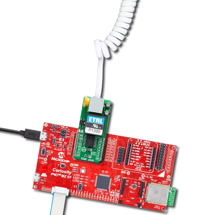
EPOS Module Click
Dev. board
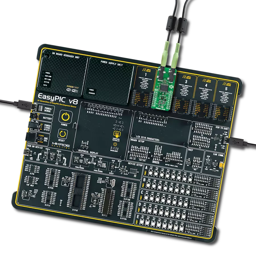
EasyPIC PRO v8
Compiler
NECTO Studio
MCU
PIC18F96J94
Enable secure, low-power modem communication for EPOS terminals and remote systems ideal for reliable data transfer in industrial control and security applications
A
A
Hardware Overview
How does it work?
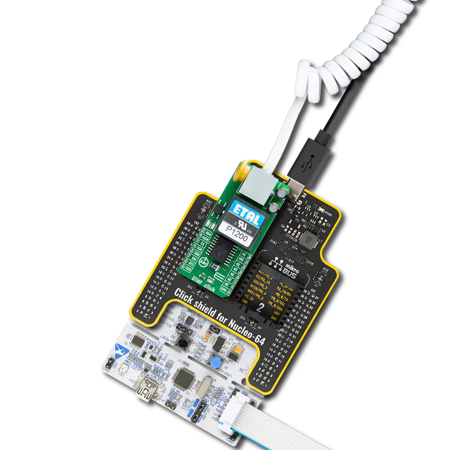
EPOS Module Click is based on the CMX869B, a multi-standard v.32 bis modem from CML Micro, which supports multiple protocols while offering low power consumption. This low-power modem solution is designed for applications involving EPOS (Electronic Point of Sale) terminals and telephone-based systems. The CMX869B supports standards such as ITU V.32 bis, V.22 bis, V.22, V.21, and Bell 202 and 103, making it adaptable for numerous communication scenarios. It operates at data rates of up to 14.400bps and features automatic fallback to 4.800bps, with capabilities like retrain rate re-negotiation and automatic detection of V.22 and V.22 bis modems. This Click board™ is ideal for use in EPOS terminals, telephone telemetry systems, remote utility meter reading, security systems, industrial control, and other applications. In addition to its robust modem
functions, the CMX869B includes a high-quality DTMF (Dual-Tone Multi-Frequency) encoder and decoder, making it suitable for managing call signaling and detection in telephone systems. The modem can also transmit and detect user-programmed single and dual-tone signals, as well as handle modem calling and answering tones, ensuring compatibility with various proprietary communication protocols beyond standard modem operations. The Click board™ also offers a fully isolated EPOS/telephone-based connection, thanks to its built-in P1200 transformer, which ensures smooth communication while providing complete electrical isolation. Data and control exchanges between the CMX869B and the host MCU are made through a C-BUS interface, compatible with a standard 4-wire SPI interface of the mikroBUS™ socket. The board also uses the mikroBUS™
socket's IRQ pin for interrupt requests related to call states like busy, dialing, and connected statuses, a red RING LED to indicate ringing signals, and a blue HOOK LED that serves as a hookswitch indicator to manage the line interface's connectivity status (0-OFF, 1-ON). An additional feature of the CMX869B is the Powersave mode, which conserves energy by deactivating all circuits except the essential C-BUS (SPI) interface. This Click board™ can be operated only with a 3.3V logic voltage level. The board must perform appropriate logic voltage level conversion before using MCUs with different logic levels. Also, it comes equipped with a library containing functions and an example code that can be used as a reference for further development.

Features overview
Development board
EasyPIC PRO v8 is a development board specially designed for the needs of rapid development of embedded applications. It supports many high pin count 8-bit PIC microcontrollers from Microchip, regardless of their number of pins, and a broad set of unique functions, such as the first-ever embedded debugger/programmer over WiFi. The development board is well organized and designed so that the end-user has all the necessary elements, such as switches, buttons, indicators, connectors, and others, in one place. Thanks to innovative manufacturing technology, EasyPIC PRO v8 provides a fluid and immersive working experience, allowing access anywhere and under
any circumstances at any time. Each part of the EasyPIC PRO v8 development board contains the components necessary for the most efficient operation of the same board. In addition to the advanced integrated CODEGRIP programmer/debugger module, which offers many valuable programming/debugging options and seamless integration with the Mikroe software environment, the board also includes a clean and regulated power supply module for the development board. It can use a wide range of external power sources, including a battery, an external 12V power supply, and a power source via the USB Type-C (USB-C) connector.
Communication options such as USB-UART, USB DEVICE, and Ethernet are also included, including the well-established mikroBUS™ standard, a standardized socket for the MCU card (SiBRAIN standard), and two display options (graphical and character-based LCD). EasyPIC PRO v8 is an integral part of the Mikroe ecosystem for rapid development. Natively supported by Mikroe software tools, it covers many aspects of prototyping and development thanks to a considerable number of different Click boards™ (over a thousand boards), the number of which is growing every day.

Microcontroller Overview
MCU Card / MCU
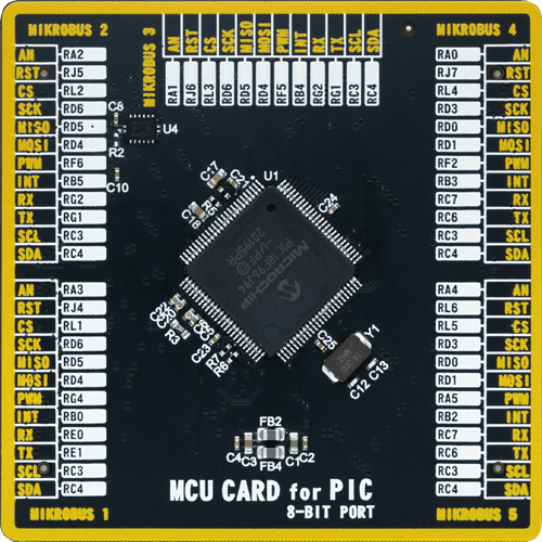
Type
8th Generation
Architecture
PIC
MCU Memory (KB)
64
Silicon Vendor
Microchip
Pin count
100
RAM (Bytes)
3862
Used MCU Pins
mikroBUS™ mapper
Take a closer look
Click board™ Schematic

Step by step
Project assembly

Start by selecting your development board and Click board™. Begin with the EasyPIC PRO v8 as your development board.


Software Support
Library Description
This library contains API for EPOS Module Click driver.
Key functions:
eposmodule_handshake_init- This function performs a handshake init which resets the device settings to default.eposmodule_dial- This function dials the selected number by alternating between DTMF and No-tone.eposmodule_send_message- This function sends an array of bytes via V.23 FSK 1200bps modem in start-stop 8.1 mode.
Open Source
Code example
The complete application code and a ready-to-use project are available through the NECTO Studio Package Manager for direct installation in the NECTO Studio. The application code can also be found on the MIKROE GitHub account.
/*!
 * @file main.c
 * @brief EPOS Module Click example
 *
 * # Description
 * This example demonstrates the use of EPOS Module Click board by showing
 * the communication between the two Click boards connected to PBX system.
 *
 * The demo application is composed of two sections :
 *
 * ## Application Init
 * Initializes the driver and logger, and displays the selected application mode.
 *
 * ## Application Task
 * Dialing application mode:
 * - Resets the device settings and dials the selected number. If a call is answered
 * it starts sending desired messages every couple of seconds with constantly checking
 * if a call is still in progress or it's terminated from the other side.
 * Answering application mode:
 * - Resets the device settings and waits for an incoming call indication, answers the call,
 * and waits for a desired number of messages. The call is terminated after all messages
 * are received successfully.
 *
 * @note
 * We have used a Yeastar S20 VoIP PBX system for the test, where the Click boards are
 * connected to ports 1 and 2 configured as FXS extension with numbers 1000 and 1001 (dialer).
 *
 * @author Stefan Filipovic
 *
 */

#include "board.h"
#include "log.h"
#include "eposmodule.h"

// Demo aplication selection macros
#define APP_DIALING                 0
#define APP_ANSWERING               1
#define DEMO_APP                    APP_DIALING

// Dialing application settings - a dial number and text to send (must end with CRLF - \r\n)
#define DIAL_NUMBER                 "1000"
#define TEXT_TO_SEND                "MIKROE - EPOS Module Click\r\n"

// Answering application settings - a number of successfully received messages before call termination
#define NUM_MESSAGES                5u

static eposmodule_t eposmodule;
static log_t logger;

void application_init ( void )
{
    log_cfg_t log_cfg;  /**< Logger config object. */
    eposmodule_cfg_t eposmodule_cfg;  /**< Click config object. */

    /**
     * Logger initialization.
     * Default baud rate: 115200
     * Default log level: LOG_LEVEL_DEBUG
     * @note If USB_UART_RX and USB_UART_TX
     * are defined as HAL_PIN_NC, you will
     * need to define them manually for log to work.
     * See @b LOG_MAP_USB_UART macro definition for detailed explanation.
     */
    LOG_MAP_USB_UART( log_cfg );
    log_init( &logger, &log_cfg );
    log_info( &logger, " Application Init " );

    // Click initialization.
    eposmodule_cfg_setup( &eposmodule_cfg );
    EPOSMODULE_MAP_MIKROBUS( eposmodule_cfg, MIKROBUS_1 );
    if ( SPI_MASTER_ERROR == eposmodule_init( &eposmodule, &eposmodule_cfg ) )
    {
        log_error( &logger, " Communication init." );
        for ( ; ; );
    }

#if ( DEMO_APP == APP_DIALING )
    log_printf( &logger, " Application Mode: Dialing\r\n" );
#elif ( DEMO_APP == APP_ANSWERING )
    log_printf( &logger, " Application Mode: Answering\r\n" );
#else
    #error "Selected application mode is not supported!"
#endif

    log_info( &logger, " Application Task " );
}

void application_task ( void )
{
    uint8_t state = EPOSMODULE_STATE_IDLE;
    uint32_t time_cnt = 0;
    uint8_t msg_cnt = 0;

    eposmodule_handshake_init ( &eposmodule );

#if ( DEMO_APP == APP_DIALING )
    log_printf( &logger, "\r\n Hook OFF\r\n" );
    eposmodule_hook_off ( &eposmodule );
    Delay_ms ( 1000 );
    Delay_ms ( 1000 );
    Delay_ms ( 1000 );
    Delay_ms ( 1000 );
    log_printf( &logger, " Dial: %s\r\n", ( char * ) DIAL_NUMBER );
    eposmodule_dial ( &eposmodule, DIAL_NUMBER );
    eposmodule.rx_mode &= EPOSMODULE_RX_LEVEL_MASK; // No change in rx level setting
    eposmodule.rx_mode |= ( EPOSMODULE_RX_MODE_DTMF_TONES | EPOSMODULE_RX_TONE_DETECT_CALL_PROG );
    eposmodule_set_receive_mode ( &eposmodule, eposmodule.rx_mode );
    for ( ; ; )
    {
        Delay_ms ( 1 );
        if ( !eposmodule_get_irq_pin ( &eposmodule ) )
        {
            time_cnt = 0;
            state = EPOSMODULE_STATE_IRQ_SET;
        }
        if ( ( EPOSMODULE_STATE_IRQ_SET == state ) && !eposmodule_call_progress ( &eposmodule ) )
        {
            if ( time_cnt < EPOSMODULE_TIMING_BUSY )
            {
                log_printf( &logger, " Busy\r\n" );
                break;
            }
            else if ( time_cnt < EPOSMODULE_TIMING_DISCONNECTED )
            {
                log_printf( &logger, " Disconnected\r\n" );
                break;
            }
            else if ( time_cnt < EPOSMODULE_TIMING_RINGING )
            {
                log_printf( &logger, " Ringing\r\n" );
                state = EPOSMODULE_STATE_RINGING;
            }
        }
        if ( ( EPOSMODULE_STATE_RINGING == state ) && ( time_cnt > EPOSMODULE_TIMING_CALL_PROGRESS ) )
        {
            log_printf( &logger, " Call in progress\r\n" );
            state = EPOSMODULE_STATE_CALL_IN_PROGRESS;
            time_cnt = 0;
        }
        if ( ( EPOSMODULE_STATE_CALL_IN_PROGRESS == state ) && !( time_cnt % EPOSMODULE_TIMING_SEND_MESSAGE ) )
        {
            log_printf( &logger, " Send message %u\r\n", ( uint16_t ) msg_cnt++ );
            eposmodule_send_message ( &eposmodule, TEXT_TO_SEND, strlen ( TEXT_TO_SEND ) );
        }
        if ( time_cnt++ > EPOSMODULE_TIMEOUT_CALL_PROGRESS )
        {
            log_printf( &logger, " Timeout\r\n" );
            break;
        }
    }
    log_printf( &logger, " Hook ON\r\n" );
    eposmodule_hook_on ( &eposmodule );
    Delay_ms ( 1000 );
    Delay_ms ( 1000 );
    Delay_ms ( 1000 );
    Delay_ms ( 1000 );
#elif ( DEMO_APP == APP_ANSWERING )
    uint8_t rx_data = 0;
    uint8_t msg_end_buff[ 2 ] = { 0 };

    log_printf( &logger, "\r\n Waiting for a call...\r\n" );

    while ( !eposmodule_ring_detect ( &eposmodule ) );

    Delay_ms ( 1000 );
    log_printf( &logger, " Hook OFF\r\n" );
    eposmodule_hook_off ( &eposmodule );
    Delay_ms ( 1000 );
    log_printf( &logger, " Waiting for %u messages...\r\n", ( uint16_t ) NUM_MESSAGES );
    eposmodule.rx_mode &= EPOSMODULE_RX_LEVEL_MASK; // No change in rx level setting
    eposmodule.rx_mode |= ( EPOSMODULE_RX_MODE_V23_FSK_1200 | EPOSMODULE_RX_DATA_FORMAT_SS_NO_OVS |
                            EPOSMODULE_RX_DATA_PARITY_8_NO_PAR );
    eposmodule_set_receive_mode ( &eposmodule, eposmodule.rx_mode );

    for ( ; ; )
    {
        Delay_ms ( 1 );
        if ( !eposmodule_get_irq_pin ( &eposmodule ) )
        {
            if ( EPOSMODULE_STATE_IDLE != state )
            {
                log_printf( &logger, "\r\n Disconnected\r\n" );
                break;
            }
            log_printf( &logger, " Message %u: ", ( uint16_t ) msg_cnt );
            state = EPOSMODULE_STATE_IRQ_SET;
            time_cnt = 0;
        }
        if ( ( EPOSMODULE_STATE_IRQ_SET == state ) && !( time_cnt % EPOSMODULE_TIMING_RX_READY ) )
        {
            if ( eposmodule_unscram_1s_det ( &eposmodule ) && eposmodule_rx_ready ( &eposmodule ) )
            {
                eposmodule_receive_data ( &eposmodule, &rx_data );
                if ( ( ( ' ' <= rx_data ) && ( '~' >= rx_data ) ) ||
                     ( '\r' == rx_data ) || ( '\n' == rx_data ) )
                {
                    log_printf( &logger, "%c", ( char ) rx_data );
                }
                if ( '\r' == rx_data )
                {
                    msg_end_buff[ 0 ] = rx_data;
                }
                else if ( '\n' == rx_data )
                {
                    msg_end_buff[ 1 ] = rx_data;
                }
                else
                {
                    msg_end_buff[ 0 ] = 0;
                    msg_end_buff[ 1 ] = 0;
                }
            }
            if ( ( '\r' == msg_end_buff[ 0 ] ) && ( '\n' == msg_end_buff[ 1 ] ) )
            {
                msg_end_buff[ 0 ] = 0;
                msg_end_buff[ 1 ] = 0;
                state = EPOSMODULE_STATE_IDLE;
                if ( NUM_MESSAGES == ++msg_cnt )
                {
                    Delay_ms ( 100 );
                    log_printf( &logger, " Terminate call\r\n" );
                    Delay_ms ( 100 );
                    break;
                }
            }
        }
        if ( time_cnt++ > EPOSMODULE_TIMING_WAIT_FOR_MESSAGE )
        {
            log_printf( &logger, "\r\n Timeout\r\n" );
            break;
        }
    }
    log_printf( &logger, " Hook ON\r\n" );
    eposmodule_hook_on ( &eposmodule );
    Delay_ms ( 1000 );
    Delay_ms ( 1000 );
    Delay_ms ( 1000 );
    Delay_ms ( 1000 );
#endif
}

int main ( void )
{
    /* Do not remove this line or clock might not be set correctly. */
    #ifdef PREINIT_SUPPORTED
    preinit();
    #endif

    application_init( );

    for ( ; ; )
    {
        application_task( );
    }

    return 0;
}

// ------------------------------------------------------------------------ END
Additional Support
Resources
Category:Signal Processing