Create the perfect climate for your success with ENS210 and TM4C1294NCZAD
Be in sync with nature's rhythm

Published Nov 07, 2023
Click board™
Temp&Hum 6 Click
Dev. board
UNI-DS v8
Compiler
NECTO Studio
MCU
TM4C1294NCZAD
We help you measure, manage, and master your environment, ensuring that your surroundings are in harmony with your needs and goals
A
A
Hardware Overview
How does it work?
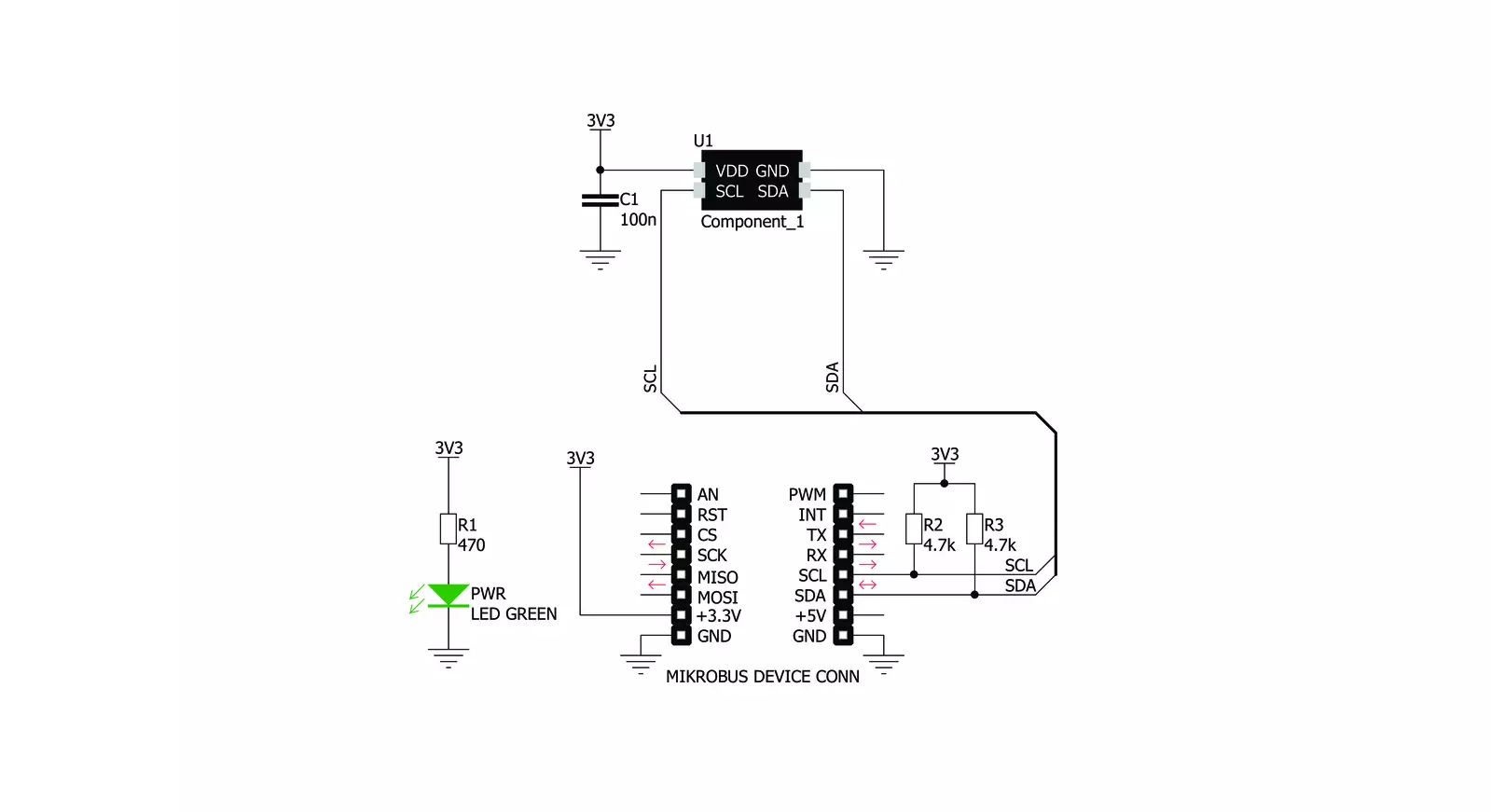
Temp&Hum 6 Click is bsaed on the ENS210, a relative humidity and temperature sensor with I²C Interface, from ScioSense. This sensor IC integrates two very accurate sensing components: temperature sensor, and relative humidity sensor. Thanks to an integrated logic back-end section, the IC can output calibrated readings from both sensors in human-readable format (%RH, and K). The ENS210 incorporates a high accuracy thermal sensor, which can measure the temperature in the range between -40°C and 100°C while retaining accuracy of ±0.5°C. The accuracy is even greater if the range is narrowed down: when used over the range between 0°C and 70°C, the typical accuracy is ±0.2°C. Also, the repeatability of the temperature measurement is very good, in the range of ±0.1°C. The ENS210 is very reliable. It can be used for prolonged periods of time, as it has a very low thermal drift of only 0.005°C per year. After the measurement has been converted by the A/D converter which uses a relatively new hybrid-mode
technology (Zoom ADC), it is fed to a logic back-end, which applies factory-calibrated correction, and converts the raw data into Kelvins. Note that the sensor will take some time to accommodate to the ambient temperature, especially if the temperature changes quickly, considering the thermal conductivity of the PCB itself. However, the Click board™ surface is not very large, resulting in lower thermal inertia. The humidity sensor is a capacitor-based sensor, which consists of a humidity-sensitive large-area capacitor. The humidity-sensitive layer allows the capacitance changes proportional to relative humidity. The capacitance has a linear dependence on temperature, which ensures high accuracy. However, the accuracy of the relative humidity sensor changes with the ambient temperature, as well as with the %RH. The datasheet of the ENS210 offers an absolute accuracy map, covering a range of different %RH and °C values. The RH sensor accuracy varies in the range between ±2.5% and ±5.5%, depending on the
measuring conditions. This table can be used to check the exact accuracy for some specific conditions. After the measurement has been converted by a high-precision 2nd order sigma-delta ADC, the logic back-end section applies the factory-calibrated correction and converts the raw data into %RH value. Note that the capacitor-based humidity sensors commonly suffer from a small hysteresis that might occur if the sensor is used in very humid conditions for prolonged periods of time. However, this hysteresis is not irreversible. The ENS210 does not exhibit a significant hysteresis effect. The datasheet specifies it to be ±0.7 %RH in the range between 20% to 90% RH, and ambient temperature of 25 °C. Temp&Hum 6 click uses the I2C communication interface. It has pull-up resistors connected to the mikroBUS™ 3.3V rail. A proper conversion of logic voltage levels should be applied before the Click board™ is used with MCUs operated with 5V.

Features overview
Development board
UNI-DS v8 is a development board specially designed for the needs of rapid development of embedded applications. It supports a wide range of microcontrollers, such as different STM32, Kinetis, TIVA, CEC, MSP, PIC, dsPIC, PIC32, and AVR MCUs regardless of their number of pins, and a broad set of unique functions, such as the first-ever embedded debugger/programmer over WiFi. The development board is well organized and designed so that the end-user has all the necessary elements, such as switches, buttons, indicators, connectors, and others, in one place. Thanks to innovative manufacturing technology, UNI-DS v8 provides a fluid and immersive working experience, allowing access anywhere and under any
circumstances at any time. Each part of the UNI-DS v8 development board contains the components necessary for the most efficient operation of the same board. An advanced integrated CODEGRIP programmer/debugger module offers many valuable programming/debugging options, including support for JTAG, SWD, and SWO Trace (Single Wire Output)), and seamless integration with the Mikroe software environment. Besides, it also includes a clean and regulated power supply module for the development board. It can use a wide range of external power sources, including a battery, an external 12V power supply, and a power source via the USB Type-C (USB-C) connector. Communication options such as USB-UART, USB
HOST/DEVICE, CAN (on the MCU card, if supported), and Ethernet is also included. In addition, it also has the well-established mikroBUS™ standard, a standardized socket for the MCU card (SiBRAIN standard), and two display options for the TFT board line of products and character-based LCD. UNI-DS v8 is an integral part of the Mikroe ecosystem for rapid development. Natively supported by Mikroe software tools, it covers many aspects of prototyping and development thanks to a considerable number of different Click boards™ (over a thousand boards), the number of which is growing every day.

Microcontroller Overview
MCU Card / MCU
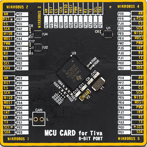
Type
8th Generation
Architecture
ARM Cortex-M4
MCU Memory (KB)
1024
Silicon Vendor
Texas Instruments
Pin count
212
RAM (Bytes)
262144
Used MCU Pins
mikroBUS™ mapper
Take a closer look
Click board™ Schematic
Step by step
Project assembly

Start by selecting your development board and Click board™. Begin with the UNI-DS v8 as your development board.


Software Support
Library Description
This library contains API for Temp&Hum 6 Click driver.
Key functions:
temphum6_read_temperature- This function returns read Temperature data.temphum6_read_relative_huminidy- This function returns read relative Humidity data.temphum6_get_part_id- This function returns the device part id.
Open Source
Code example
The complete application code and a ready-to-use project are available through the NECTO Studio Package Manager for direct installation in the NECTO Studio. The application code can also be found on the MIKROE GitHub account.
/*!
 * \file
 * \brief TempHum6 Click example
 *
 * # Description
 * This application emasures temperature and humidity.
 *
 * The demo application is composed of two sections :
 *
 * ## Application Init
 * Initialization driver init and reset device and read Part ID
 *
 * ## Application Task
 * Reads Temperature and Huminidy data and logs this data to USBUART every 1sec.
 *
 *
 * \author MikroE Team
 *
 */
// ------------------------------------------------------------------- INCLUDES

#include "board.h"
#include "log.h"
#include "temphum6.h"

// ------------------------------------------------------------------ VARIABLES

static temphum6_t temphum6;
static log_t logger;

// ------------------------------------------------------ APPLICATION FUNCTIONS

void application_init ( void )
{
    log_cfg_t log_cfg;
    temphum6_cfg_t cfg;
    uint16_t part_id;

    /**
     * Logger initialization.
     * Default baud rate: 115200
     * Default log level: LOG_LEVEL_DEBUG
     * @note If USB_UART_RX and USB_UART_TX
     * are defined as HAL_PIN_NC, you will
     * need to define them manually for log to work.
     * See @b LOG_MAP_USB_UART macro definition for detailed explanation.
     */
    LOG_MAP_USB_UART( log_cfg );
    log_init( &logger, &log_cfg );
    log_info( &logger, "---- Application Init ----" );

    //  Click initialization.

    temphum6_cfg_setup( &cfg );
    TEMPHUM6_MAP_MIKROBUS( cfg, MIKROBUS_1 );
    temphum6_init( &temphum6, &cfg );

    temphum6_reset( &temphum6 );

    part_id = temphum6_get_part_id( &temphum6 );
    if ( part_id == TEMPHUM6_PART_ID )
    {
        log_printf( &logger, "Device OK - read ID is OK  0x%x\r\n", part_id );
    }
    else
    {
        log_printf( &logger, "Device ERROR - read ID is NOT OK 0x%x\r\n", part_id  );
        for ( ; ; );
    }
}

void application_task ( void )
{
    //  Task implementation.

    float temp;
    float hum;

    temp = temphum6_read_temperature( &temphum6, TEMPHUM6_TEMP_IN_CELSIUS );
    log_printf( &logger, "Temperature is %.2f C\r\n", temp );

    hum = temphum6_read_relative_huminidy( &temphum6 );
    log_printf( &logger, "Huminidy is %.2f %%RH\r\n", hum );

    log_printf( &logger, "------------------\r\n");
    Delay_ms ( 1000 );
}

int main ( void )
{
    /* Do not remove this line or clock might not be set correctly. */
    #ifdef PREINIT_SUPPORTED
    preinit();
    #endif

    application_init( );

    for ( ; ; )
    {
        application_task( );
    }

    return 0;
}

// ------------------------------------------------------------------------ END


