Enable real-time force monitoring using FSS1500NGT and TM4C129ENCPDT
Transforming forces into measurable wisdom
Published Aug 29, 2023
Click board™
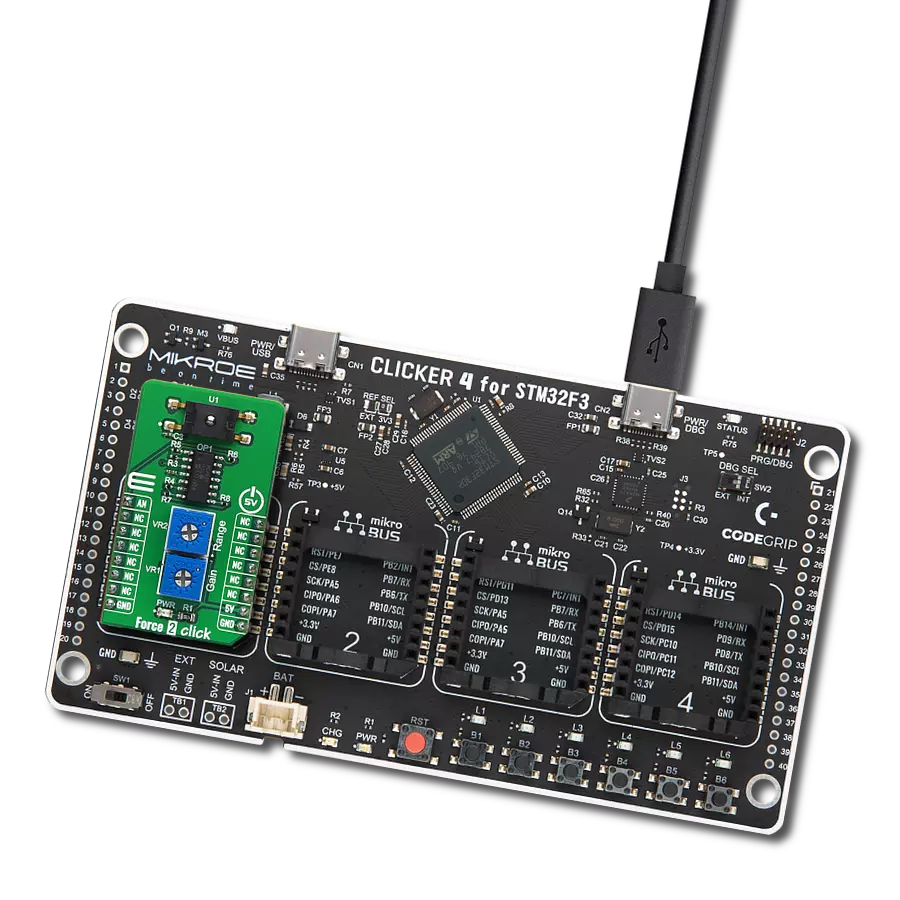
Force 2 Click
Dev. board
Fusion for Tiva v8
Compiler
NECTO Studio
MCU
TM4C129ENCPDT
Elevate your projects with actionable force measurements for improved performance
A
A
Hardware Overview
How does it work?
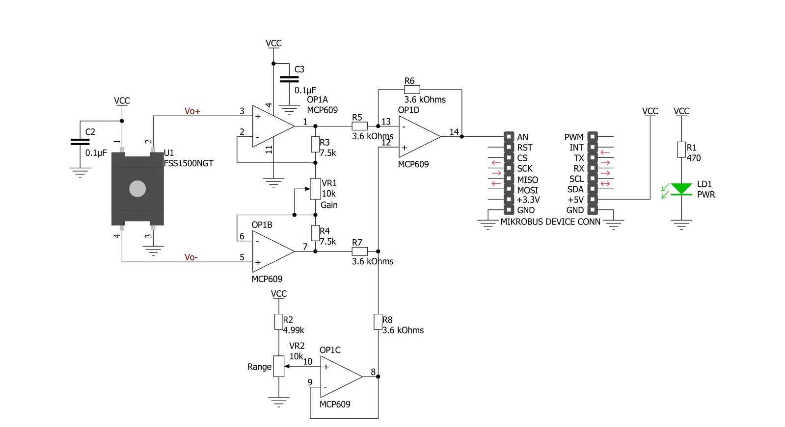
Force 2 Click is based on the FSS1500NGT, a force sensor from Honeywell that uses a specialized piezoresistive micromachined silicon sensing element. The low-power, unamplified, uncompensated Wheatstone bridge circuit design provides inherently stable mV output over the force range. The sensor package design incorporates patented modular construction. Using innovative elastomeric technology and engineered molded plastics results in load excitation capacities up to 60 N (range dependent). The stainless steel ball provides excellent mechanical stability and is suitable for various potential medical and commercial applications. Force 2 Click also contains all the needed circuitry required to get precise measurements from the sensor. It includes four
operational amplifiers, forming one differential amplifier with a voltage adder, which can be used to set the measurement range. Gain setting is also available to enable users to easily set this board according to various needs. Range and gain are set using the onboard multi-turn trimmers VR1 and VR2. That way, it is ensured that the precise setting can easily be done. The output of the differential amplifier is connected to the analog pin AN of mikroBUS™. Force sensors operate on the principle that the resistance of silicon-implanted piezoresistors will change when the resistors flex under applied force. The sensor directly concentrates force from the applications through the stainless steel ball to the silicon-sensing element. The amount of resistance changes in proportion to the amount of force
being applied. This change in circuit resistance results in a corresponding mV output level change. Low voltage supply allows for use in many battery-powered applications. Force 2 Click has an FSS1500NGT force sensor on it, and the force sensing range is 0-15N with overforce (the maximum force that may safely be applied to the product for it to remain in specification once force is returned to the operating force range) up to 45N. This Click board™ can be operated only with a 5V logic voltage level. The board must perform appropriate logic voltage level conversion before using MCUs with different logic levels. Also, it comes equipped with a library containing functions and an example code that can be used as a reference for further development.


Features overview
Development board
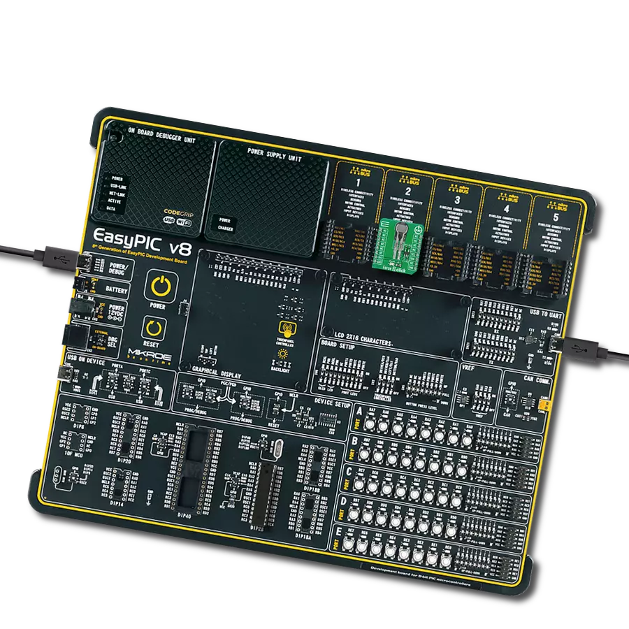
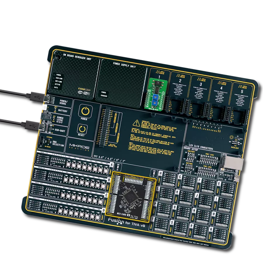
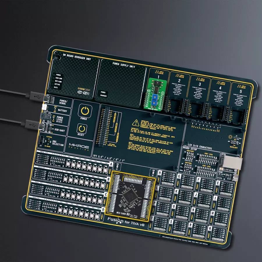
Fusion for TIVA v8 is a development board specially designed for the needs of rapid development of embedded applications. It supports a wide range of microcontrollers, such as different 32-bit ARM® Cortex®-M based MCUs from Texas Instruments, regardless of their number of pins, and a broad set of unique functions, such as the first-ever embedded debugger/programmer over a WiFi network. The development board is well organized and designed so that the end-user has all the necessary elements, such as switches, buttons, indicators, connectors, and others, in one place. Thanks to innovative manufacturing technology, Fusion for TIVA v8 provides a fluid and immersive working experience, allowing access
anywhere and under any circumstances at any time. Each part of the Fusion for TIVA v8 development board contains the components necessary for the most efficient operation of the same board. An advanced integrated CODEGRIP programmer/debugger module offers many valuable programming/debugging options, including support for JTAG, SWD, and SWO Trace (Single Wire Output)), and seamless integration with the Mikroe software environment. Besides, it also includes a clean and regulated power supply module for the development board. It can use a wide range of external power sources, including a battery, an external 12V power supply, and a power source via the USB Type-C (USB-C) connector.
Communication options such as USB-UART, USB HOST/DEVICE, CAN (on the MCU card, if supported), and Ethernet is also included. In addition, it also has the well-established mikroBUS™ standard, a standardized socket for the MCU card (SiBRAIN standard), and two display options for the TFT board line of products and character-based LCD. Fusion for TIVA v8 is an integral part of the Mikroe ecosystem for rapid development. Natively supported by Mikroe software tools, it covers many aspects of prototyping and development thanks to a considerable number of different Click boards™ (over a thousand boards), the number of which is growing every day.

Microcontroller Overview
MCU Card / MCU

Type
8th Generation
Architecture
ARM Cortex-M4
MCU Memory (KB)
1024
Silicon Vendor
Texas Instruments
Pin count
128
RAM (Bytes)
262144
Used MCU Pins
mikroBUS™ mapper
Take a closer look
Click board™ Schematic
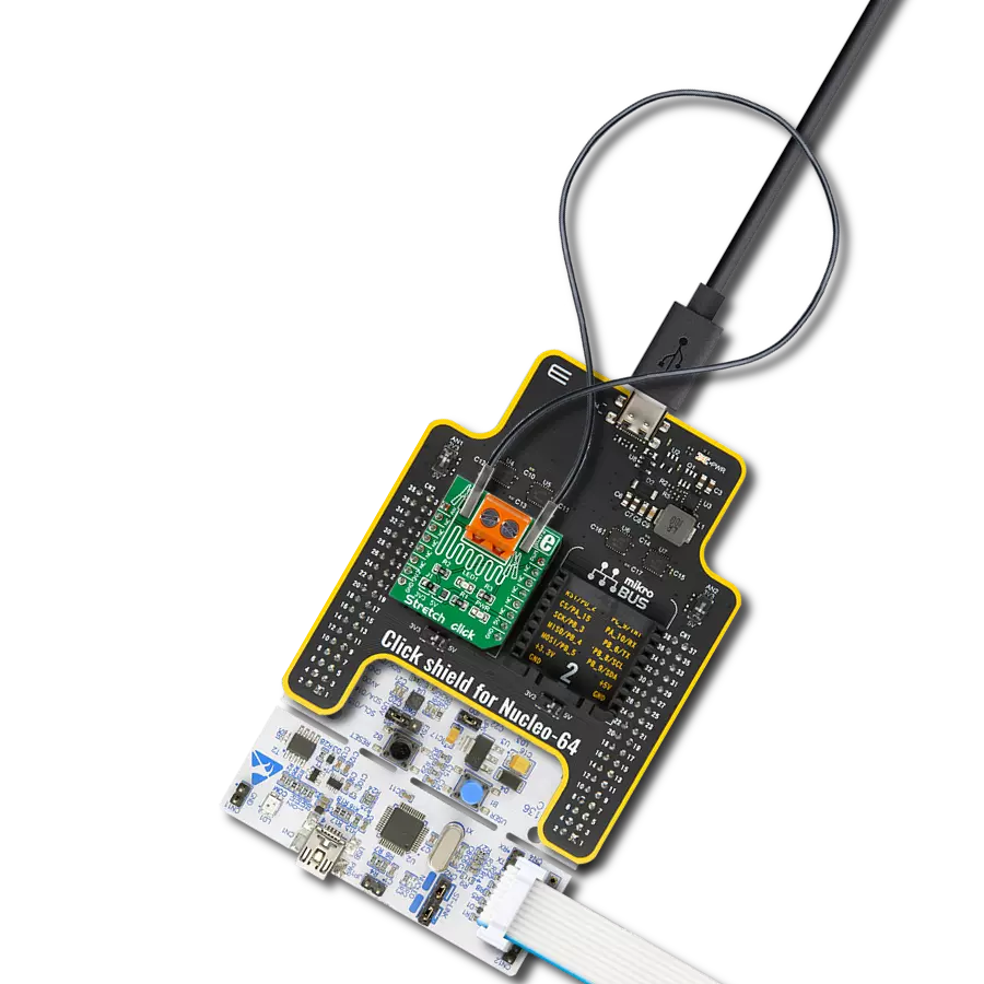
Step by step
Project assembly

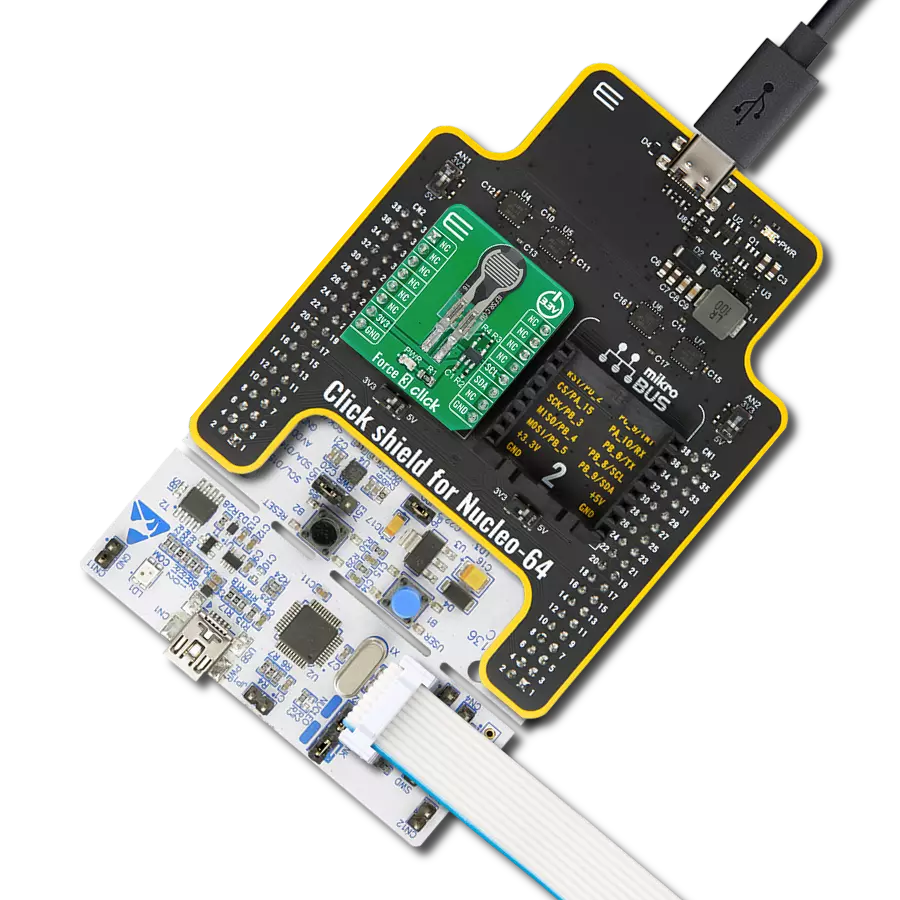
Start by selecting your development board and Click board™. Begin with the Fusion for Tiva v8 as your development board.


Software Support
Library Description
This library contains API for Force 2 Click driver.
Key functions:
force2_read_an_pin_value- This function reads results of AD conversion of the AN pinforce2_read_an_pin_voltage- This function reads results of AD conversion of the AN pin and converts them to proportional voltage level
Open Source
Code example
The complete application code and a ready-to-use project are available through the NECTO Studio Package Manager for direct installation in the NECTO Studio. The application code can also be found on the MIKROE GitHub account.
/*!
 * \file
 * \brief Force 2 Click example
 *
 * # Description
 * This example demonstrates the use of Force 2 Click board by reading and displaying
 * the voltage from AN pin and the calculated force (N) value.
 *
 * The demo application is composed of two sections :
 *
 * ## Application Init
 * Initalizes the driver and logger and makes an initial log.
 *
 * ## Application Task
 * Reads and displays the voltage from AN pin, then calculates and displays the force in N.
 *
 * @note
 * Adjust the gain and range onboard potentiometers in order to get zero N when there's no
 * force applied to the sensor.
 *
 * \author MikroE Team
 *
 */
// ------------------------------------------------------------------- INCLUDES

#include "board.h"
#include "log.h"
#include "force2.h"

// ------------------------------------------------------------------ VARIABLES

static force2_t force2;
static log_t logger;

void application_init ( void )
{
    log_cfg_t log_cfg;
    force2_cfg_t cfg;

    /**
     * Logger initialization.
     * Default baud rate: 115200
     * Default log level: LOG_LEVEL_DEBUG
     * @note If USB_UART_RX and USB_UART_TX
     * are defined as HAL_PIN_NC, you will
     * need to define them manually for log to work.
     * See @b LOG_MAP_USB_UART macro definition for detailed explanation.
     */
    LOG_MAP_USB_UART( log_cfg );
    log_init( &logger, &log_cfg );
    log_info( &logger, "---- Application Init ----" );

    //  Click initialization.
    force2_cfg_setup( &cfg );
    FORCE2_MAP_MIKROBUS( cfg, MIKROBUS_1 );
    force2_init( &force2, &cfg );

    log_printf( &logger, "--------------------\r\n" );
    log_printf( &logger, "    Force 2 Click   \r\n" );
    log_printf( &logger, "--------------------\r\n" );
    Delay_ms ( 500 );
}

void application_task ( void )
{
    float voltage = 0;
    if ( FORCE2_OK == force2_read_an_pin_voltage ( &force2, &voltage ) )
    {
        log_printf( &logger, " AN Voltage: %.3f V\r\n", voltage );
        log_printf( &logger, " Force: %.1f N\r\n",
                    FORCE2_FORCE_MAX - voltage * FORCE2_FORCE_MAX / FORCE2_VREF );
        log_printf( &logger, "-----------------------------\r\n" );
        Delay_ms ( 1000 );
    }
}

int main ( void )
{
    /* Do not remove this line or clock might not be set correctly. */
    #ifdef PREINIT_SUPPORTED
    preinit();
    #endif

    application_init( );

    for ( ; ; )
    {
        application_task( );
    }

    return 0;
}
// ------------------------------------------------------------------------ END