Enable users to tailor vibration patterns to their preferences using G0832022D and STM32L496AG
Shake up your world with control
Published Jul 22, 2025
Click board™
Vibro Motor 3 Click
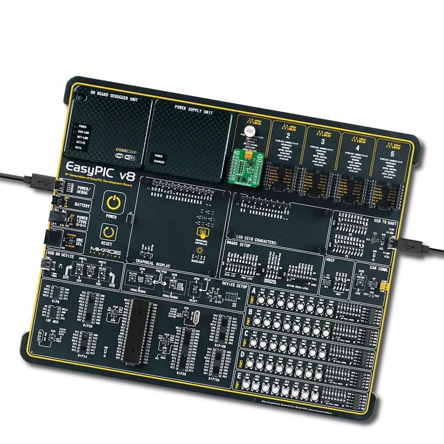
Dev. board
Discovery kit with STM32L496AG MCU
Compiler
NECTO Studio
MCU
STM32L496AG
Fine-tune your device notifications with precision, ensuring that users receive alerts in a more discreet and personalized manner
A
A
Hardware Overview
How does it work?
Vibro Motor 3 Click is based on the G0832022D, a coin-sized linear resonant actuator that generates vibration/haptic feedback in the Z plane, perpendicular to the motor's surface from Jinlong Machinery & Electronics, Inc. The G0832022D draws only 19mA at 0.6V while producing a G force of 0.55 GRMS and makes an excellent choice for applications requiring crisp haptic feedback and low power consumption. For haptic feedback applications, fast rise and fall times are critical for achieving the optimal user experience. Driven by the DRV2605, a flexible Haptic/Vibra driver from Texas Instruments, this Click board™ is designed to provide highly flexible haptic control over a standard I2C 2-Wire interface with a maximum clock frequency of 400kHz. It possesses an enabling function, routed on the CS pin
of the mikroBUS™ socket labeled as the EN, and comes up with an extensive integrated library of over 100 licensed effects that eliminates the need to design haptics waveforms. It also contains a smart-loop architecture, which allows effortless auto resonant drive for LRA motor drive. This feedback provides automatic overdrive and braking, which creates a simplified input waveform paradigm, reliable motor control, and consistent motor performance. The DRV2605 can also operate in the PWM Mode and accept the PWM signal from the PWM pin of the mikroBUS™ socket. In this mode, the DRV2605 device drives the actuator continuously until the user sets the DRV2605 to a Standby Mode or enters another interface mode. In PWM Mode, the vibration strength is controlled by the duty cycle, and
for the LRA motor, the DRV2605 automatically tracks the resonance frequency unless the LRA_OPEN_LOOP bit in register 0x1D is set. If the LRA_OPEN_LOOP bit is set, then the LRA motor is driven according to the frequency of the PWM input signal. More information about the operating modes of the DRV2605 can be found in the attached datasheet. This Click board™ can operate with either 3.3V or 5V logic voltage levels selected via the VCC SEL jumper. This way, both 3.3V and 5V capable MCUs can use the communication lines properly. Also, this Click board™ comes equipped with a library containing easy-to-use functions and an example code that can be used as a reference for further development.


Features overview
Development board
The 32L496GDISCOVERY Discovery kit serves as a comprehensive demonstration and development platform for the STM32L496AG microcontroller, featuring an Arm® Cortex®-M4 core. Designed for applications that demand a balance of high performance, advanced graphics, and ultra-low power consumption, this kit enables seamless prototyping for a wide range of embedded solutions. With its innovative energy-efficient
architecture, the STM32L496AG integrates extended RAM and the Chrom-ART Accelerator, enhancing graphics performance while maintaining low power consumption. This makes the kit particularly well-suited for applications involving audio processing, graphical user interfaces, and real-time data acquisition, where energy efficiency is a key requirement. For ease of development, the board includes an onboard ST-LINK/V2-1
debugger/programmer, providing a seamless out-of-the-box experience for loading, debugging, and testing applications without requiring additional hardware. The combination of low power features, enhanced memory capabilities, and built-in debugging tools makes the 32L496GDISCOVERY kit an ideal choice for prototyping advanced embedded systems with state-of-the-art energy efficiency.

Microcontroller Overview
MCU Card / MCU

Architecture
ARM Cortex-M4
MCU Memory (KB)
1024
Silicon Vendor
STMicroelectronics
Pin count
169
RAM (Bytes)
327680
Used MCU Pins
mikroBUS™ mapper
Take a closer look
Click board™ Schematic

Step by step
Project assembly

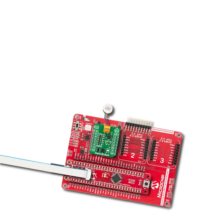
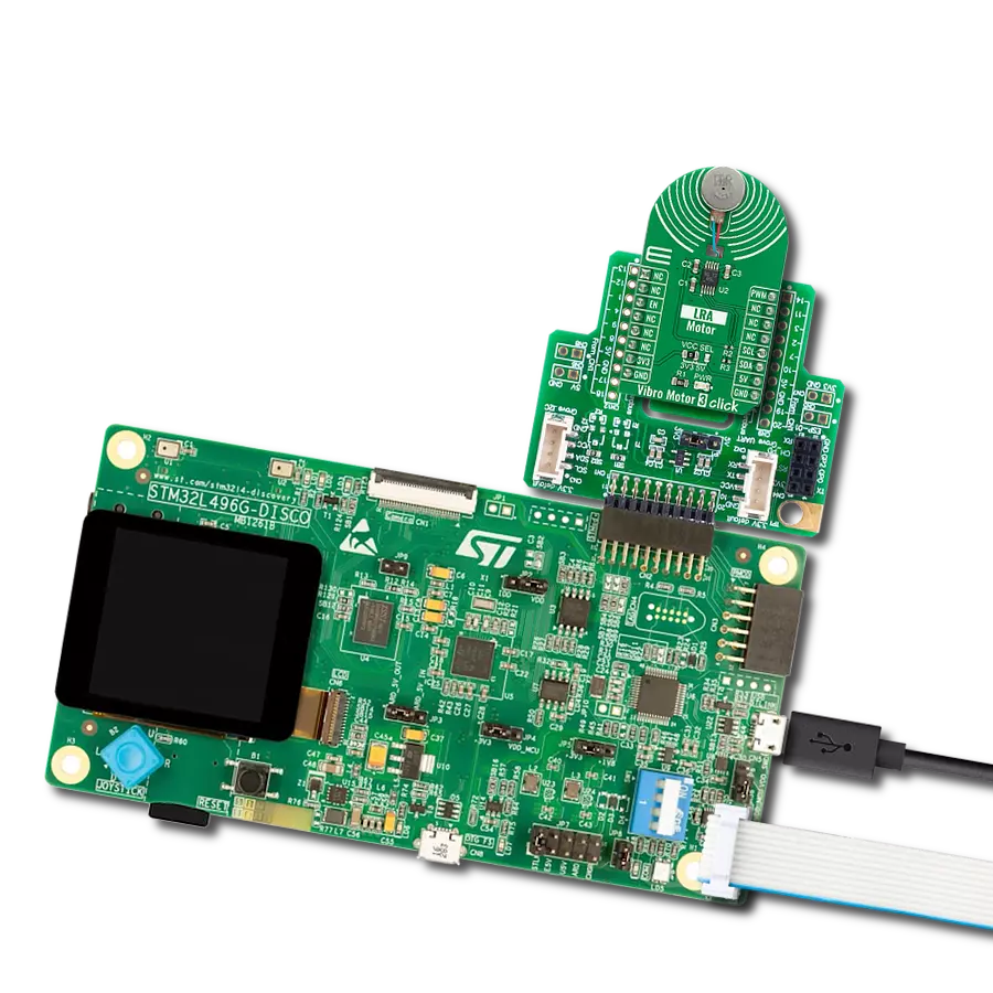
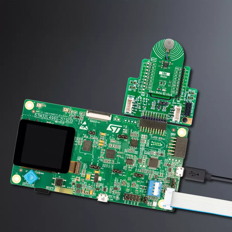
Start by selecting your development board and Click board™. Begin with the Discovery kit with STM32L496AG MCU as your development board.


Software Support
Library Description
This library contains API for Vibro Motor 3 Click driver.
Key functions:
vibromotor3_set_duty_cycle- Vibro Motor 3 sets PWM duty cyclevibromotor3_enable- Enable the device functionvibromotor3_write_byte- Generic write the byte of data function
Open Source
Code example
The complete application code and a ready-to-use project are available through the NECTO Studio Package Manager for direct installation in the NECTO Studio. The application code can also be found on the MIKROE GitHub account.
/*!
 * @file main.c
 * @brief VibroMotor3 Click example
 *
 * # Description
 * This example shows the capabilities of the Vibro Motor 3 Click board
 *
 * The demo application is composed of two sections :
 *
 * ## Application Init
 * Initalizes I2C driver, PWM driver and configures Vibro Motor 3 Click board.
 *
 * ## Application Task
 * Changing duty cycle applied in order to get different vibrations.
 *
 * @author Stefan Ilic
 *
 */

#include "board.h"
#include "log.h"
#include "vibromotor3.h"

static vibromotor3_t vibromotor3;
static log_t logger;

static float pwm_max_duty = 1;
static float pwm_duty_cycle = 0;


void application_init ( void ) {
    log_cfg_t log_cfg;  /**< Logger config object. */
    vibromotor3_cfg_t vibromotor3_cfg;  /**< Click config object. */

    /**
     * Logger initialization.
     * Default baud rate: 115200
     * Default log level: LOG_LEVEL_DEBUG
     * @note If USB_UART_RX and USB_UART_TX
     * are defined as HAL_PIN_NC, you will
     * need to define them manually for log to work.
     * See @b LOG_MAP_USB_UART macro definition for detailed explanation.
     */
    LOG_MAP_USB_UART( log_cfg );
    log_init( &logger, &log_cfg );
    log_info( &logger, " Application Init " );

    // Click initialization.
    vibromotor3_cfg_setup( &vibromotor3_cfg );
    VIBROMOTOR3_MAP_MIKROBUS( vibromotor3_cfg, MIKROBUS_1 );
    err_t init_flag = vibromotor3_init( &vibromotor3, &vibromotor3_cfg );
    if ( I2C_MASTER_ERROR == init_flag || PWM_ERROR == init_flag ) {
        log_error( &logger, " Application Init Error. " );
        log_info( &logger, " Please, run program again... " );

        for ( ; ; );
    }
    vibromotor3_enable( &vibromotor3, VIBROMOTOR3_PROPERTY_ENABLE );
    Delay_ms ( 100 );

    vibromotor3_soft_rst( &vibromotor3 );
    Delay_ms ( 100 );

    vibromotor3_default_cfg( &vibromotor3 );
    Delay_ms ( 100 );

    vibromotor3_set_duty_cycle( &vibromotor3, 0.0 );
    vibromotor3_pwm_start( &vibromotor3 );
    Delay_ms ( 100 );

    log_info( &logger, " Application Task " );
    Delay_ms ( 100 );
}

void application_task ( void ) {
    static int8_t duty_cnt = 1;
    static int8_t duty_inc = 1;
    float duty = duty_cnt / 10.0;

    vibromotor3_set_duty_cycle ( &vibromotor3, duty );
    log_printf( &logger, "> Duty: %d%%\r\n", ( uint16_t )( duty_cnt * 10 ) );

    Delay_ms ( 500 );

    if ( 10 == duty_cnt ) {
        duty_inc = -1;
    } else if ( 0 == duty_cnt ) {
        duty_inc = 1;
    }
    duty_cnt += duty_inc;
}

int main ( void )
{
    /* Do not remove this line or clock might not be set correctly. */
    #ifdef PREINIT_SUPPORTED
    preinit();
    #endif

    application_init( );

    for ( ; ; )
    {
        application_task( );
    }

    return 0;
}

// ------------------------------------------------------------------------ END
Additional Support
Resources
Category:Haptic