Empower yourself with actionable insights into UVA exposure with GUVA-C32SM and STM32F722VE
Exploring UVA with advanced sensing

Published Sep 24, 2023
Click board™
UVA Click
Dev. board
Fusion for STM32 v8
Compiler
NECTO Studio
MCU
STM32F722VE
Our powerful UVA sensing solution is engineered to provide accurate and real-time measurements of Ultraviolet A radiation, offering a valuable tool for applications ranging from sun safety and environmental monitoring to industrial processes and scientific research
A
A
Hardware Overview
How does it work?
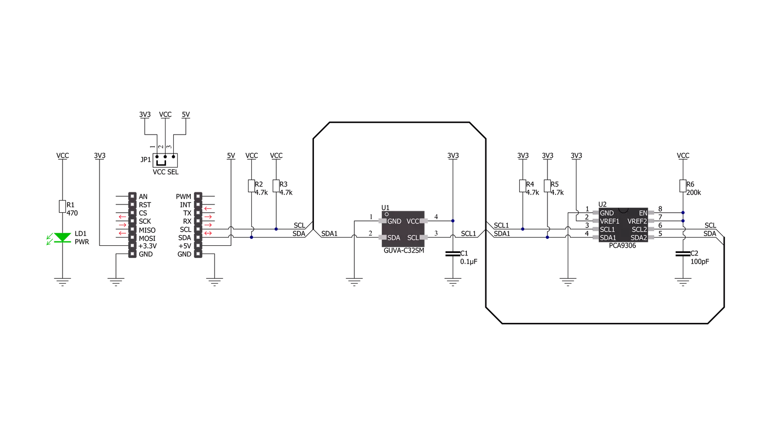
UVA Click is based on the GUVA-C32SM, an ultraviolet light sensor capable of measuring UV index between 0 and 14 from GenUV. The GUVA-C32SM contains the GaN-based chip die, integrated amplifiers, analog-to-digital converter, digital control logic, and serial interface circuit to measure detected solar UV index in the spectral range of 220-370nm. The GUVA-C32M acquires the intensity of UVA, respectively, and outputs digital count according to each intensity. A reasonable power management mode can reduce power
consumption according to specific application requirements. UVA Click communicates with MCU using the standard I2C 2-Wire interface to read data and configure settings, supporting Standard Mode operation with a clock frequency of 100kHz and Fast Mode up to 400kHz. Since the sensor for operation requires a 3.3V logic voltage level only, this Click board™ also features the PCA9306 voltage-level translator from Texas Instruments. The I2C interface bus lines are routed to the dual bidirectional voltage-level translator, allowing this
Click board™ to work properly with both 3.3V and 5V MCUs. This Click board™ can operate with either 3.3V or 5V logic voltage levels selected via the VCC SEL jumper. This way, both 3.3V and 5V capable MCUs can use the communication lines properly. Also, this Click board™ comes equipped with a library containing easy-to-use functions and an example code that can be used as a reference for further development.


Features overview
Development board
Fusion for STM32 v8 is a development board specially designed for the needs of rapid development of embedded applications. It supports a wide range of microcontrollers, such as different 32-bit ARM® Cortex®-M based MCUs from STMicroelectronics, regardless of their number of pins, and a broad set of unique functions, such as the first-ever embedded debugger/programmer over WiFi. The development board is well organized and designed so that the end-user has all the necessary elements, such as switches, buttons, indicators, connectors, and others, in one place. Thanks to innovative manufacturing technology, Fusion for STM32 v8 provides a fluid and immersive working experience, allowing
access anywhere and under any circumstances at any time. Each part of the Fusion for STM32 v8 development board contains the components necessary for the most efficient operation of the same board. An advanced integrated CODEGRIP programmer/debugger module offers many valuable programming/debugging options, including support for JTAG, SWD, and SWO Trace (Single Wire Output)), and seamless integration with the Mikroe software environment. Besides, it also includes a clean and regulated power supply module for the development board. It can use a wide range of external power sources, including a battery, an external 12V power supply, and a power source via the USB Type-C (USB-C) connector.
Communication options such as USB-UART, USB HOST/DEVICE, CAN (on the MCU card, if supported), and Ethernet is also included. In addition, it also has the well-established mikroBUS™ standard, a standardized socket for the MCU card (SiBRAIN standard), and two display options for the TFT board line of products and character-based LCD. Fusion for STM32 v8 is an integral part of the Mikroe ecosystem for rapid development. Natively supported by Mikroe software tools, it covers many aspects of prototyping and development thanks to a considerable number of different Click boards™ (over a thousand boards), the number of which is growing every day.

Microcontroller Overview
MCU Card / MCU
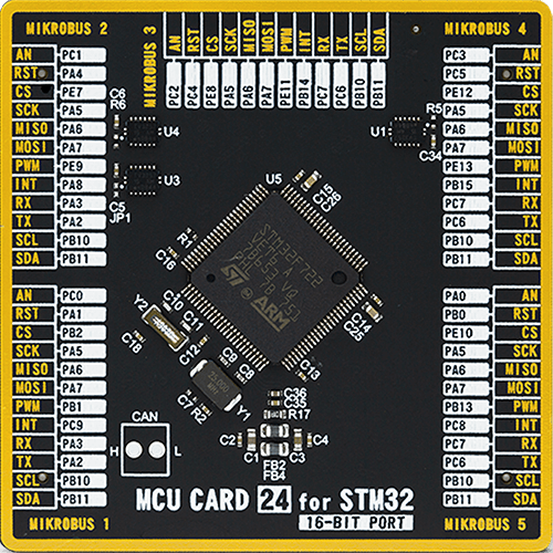
Type
8th Generation
Architecture
ARM Cortex-M7
MCU Memory (KB)
512
Silicon Vendor
STMicroelectronics
Pin count
100
RAM (Bytes)
262144
Used MCU Pins
mikroBUS™ mapper
Take a closer look
Click board™ Schematic
Step by step
Project assembly

Start by selecting your development board and Click board™. Begin with the Fusion for STM32 v8 as your development board.


Software Support
Library Description
This library contains API for UVA Click driver.
Key functions:
uva_read_data- This function reads the raw UVA data from registersuva_soft_reset- This function executes the soft reset commanduva_write_register- This function writes a data byte to the selected register by using I2C serial interface
Open Source
Code example
The complete application code and a ready-to-use project are available through the NECTO Studio Package Manager for direct installation in the NECTO Studio. The application code can also be found on the MIKROE GitHub account.
/*!
 * @file main.c
 * @brief UVA Click example
 *
 * # Description
 * This example demonstrates the use of UVA Click board by reading and displaying
 * the UVA data measurement results.
 *
 * The demo application is composed of two sections :
 *
 * ## Application Init
 * Initializes the driver and applies the Click default configuration.
 *
 * ## Application Task
 * Reads the UVA data measurements every 100ms and displays the results on the USB UART.
 *
 * @author Stefan Filipovic
 *
 */

#include "board.h"
#include "log.h"
#include "uva.h"

static uva_t uva;
static log_t logger;

void application_init ( void )
{
    log_cfg_t log_cfg;  /**< Logger config object. */
    uva_cfg_t uva_cfg;  /**< Click config object. */

    /**
     * Logger initialization.
     * Default baud rate: 115200
     * Default log level: LOG_LEVEL_DEBUG
     * @note If USB_UART_RX and USB_UART_TX
     * are defined as HAL_PIN_NC, you will
     * need to define them manually for log to work.
     * See @b LOG_MAP_USB_UART macro definition for detailed explanation.
     */
    LOG_MAP_USB_UART( log_cfg );
    log_init( &logger, &log_cfg );
    log_info( &logger, " Application Init " );

    // Click initialization.
    uva_cfg_setup( &uva_cfg );
    UVA_MAP_MIKROBUS( uva_cfg, MIKROBUS_1 );
    if ( I2C_MASTER_ERROR == uva_init( &uva, &uva_cfg ) )
    {
        log_error( &logger, " Communication init." );
        for ( ; ; );
    }

    if ( UVA_ERROR == uva_default_cfg ( &uva ) )
    {
        log_error( &logger, " Default configuration." );
        for ( ; ; );
    }

    log_info( &logger, " Application Task " );
}

void application_task ( void )
{
    uint16_t uva_data = 0;
    if ( UVA_OK == uva_read_data ( &uva, &uva_data ) )
    {
        log_printf ( &logger, " UVA data: %u \r\n\n", uva_data );
        Delay_ms ( 100 );
    }
}

int main ( void )
{
    /* Do not remove this line or clock might not be set correctly. */
    #ifdef PREINIT_SUPPORTED
    preinit();
    #endif

    application_init( );

    for ( ; ; )
    {
        application_task( );
    }

    return 0;
}

// ------------------------------------------------------------------------ END
Additional Support
Resources
Category:Optical


