Transform any space into a mesmerizing spectacle with IN-PC55TBTRGB and STM32F302VC
Customizable and immersive lighting experience
Published Jul 22, 2025
Click board™
4x4 RGB 2 Click
Dev. board
CLICKER 4 for STM32F302VCT6
Compiler
NECTO Studio
MCU
STM32F302VC
Step into a world of wonder with our solution's matrix of 16 intelligent RGB LEDs, crafting a spellbinding 4x4 display screen that enchants your surroundings with vibrant hues and captivating visual effects.
A
A
Hardware Overview
How does it work?
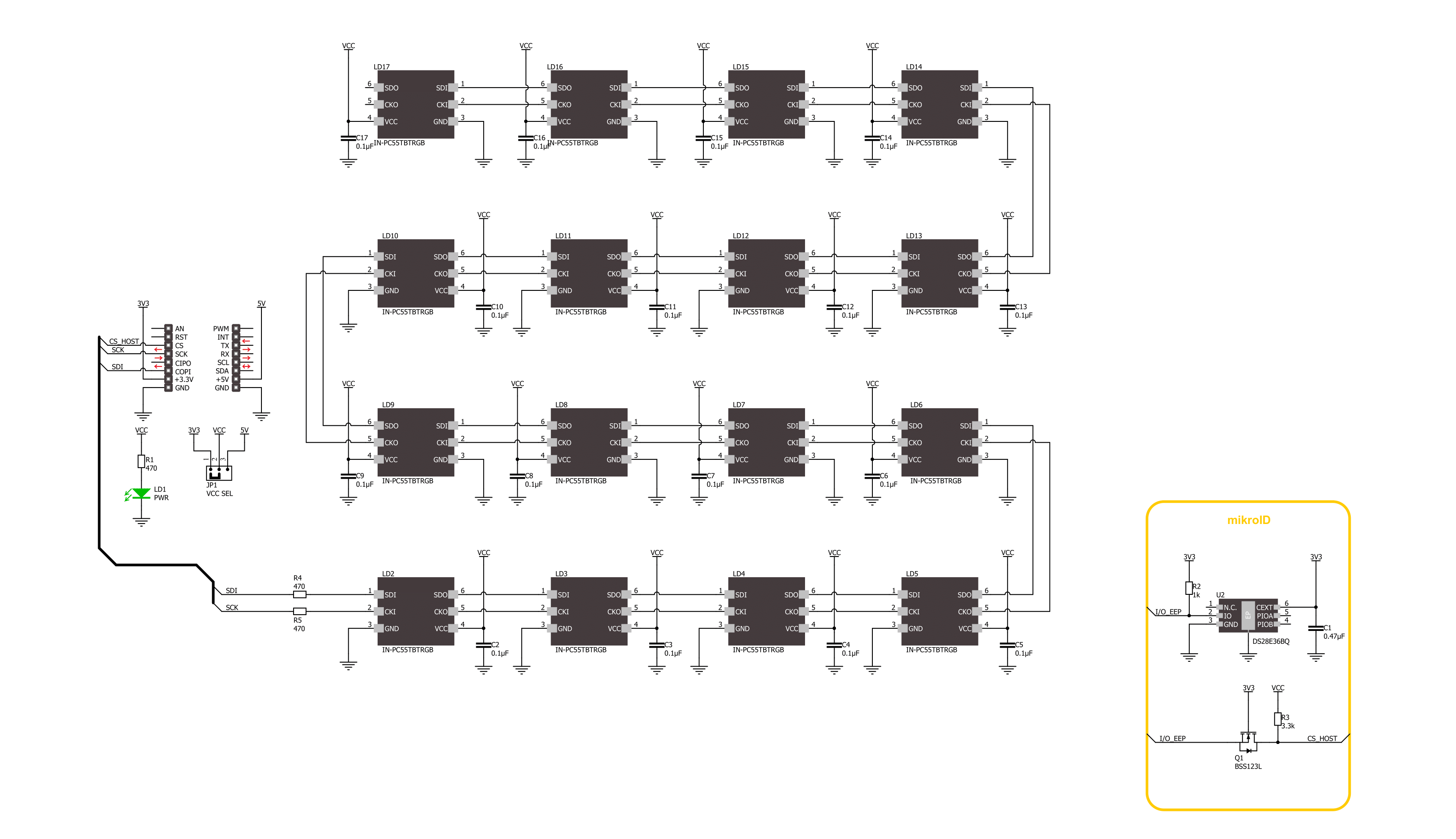
4x4 EGB 2 Click is based on 16 IN-PC55TBTRGB, RGB LEDs with an integrated IC from Inolux. The LED contains a signal decoding module, a data buffer, a built-in current circuit, and an RC oscillator in the same 5050 packages, forming a color-mixing uniformity and consistency. The LEDs can maintain a static image, thus making the perfect choice for developing an LED screen. Some other features that these LEDs have are built-in support for uninterrupted oscillation PWM, double data transmission, self-detection function-specific signal, three constant current drives, and more. The 4x4 RGB 2 Click uses a two-wire
synchronous transmission to communicate with the host MCU, routed to the SCK and the SDI pins of the mikroBUS™ socket. The maximum input serial data frequency is 30MHz. The data transmission goes from the host MCU through every single LED until the last one in a cascade manner, where the only limit is the number of the LEDs on this Click board™. The maximum LED output current is 20mA, while the LEDs' light intensity, depending on the current, varies from 300mcd at the lowest for Blue to 1500mcd at the highest for Green. Although the chain could be bigger, this is not enabled on the 4x4 RGB 2 Click.
The length of the chain can be limited only by the communication speed required to scan through all the LED devices in order to maintain a reasonable refresh speed. This Click board™ can operate with either 3.3V or 5V logic voltage levels selected via the VCC SEL jumper. This way, both 3.3V and 5V capable MCUs can use the communication lines properly. Also, this Click board™ comes equipped with a library containing easy-to-use functions and an example code that can be used as a reference for further development.

Features overview
Development board
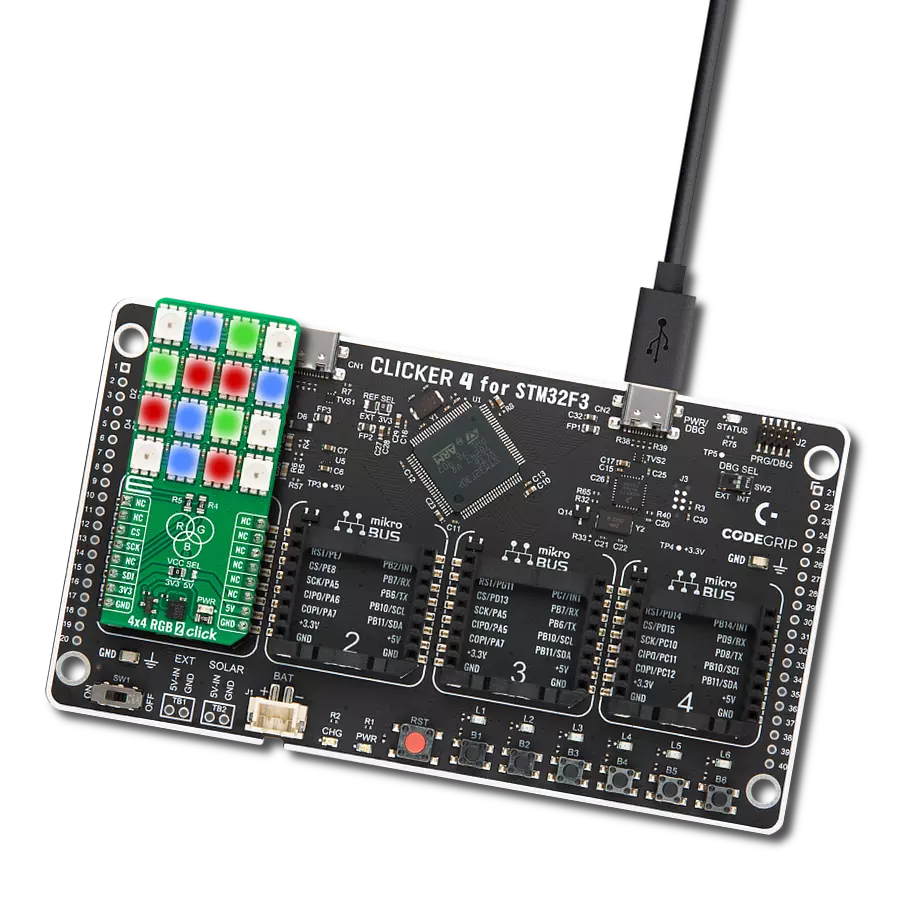
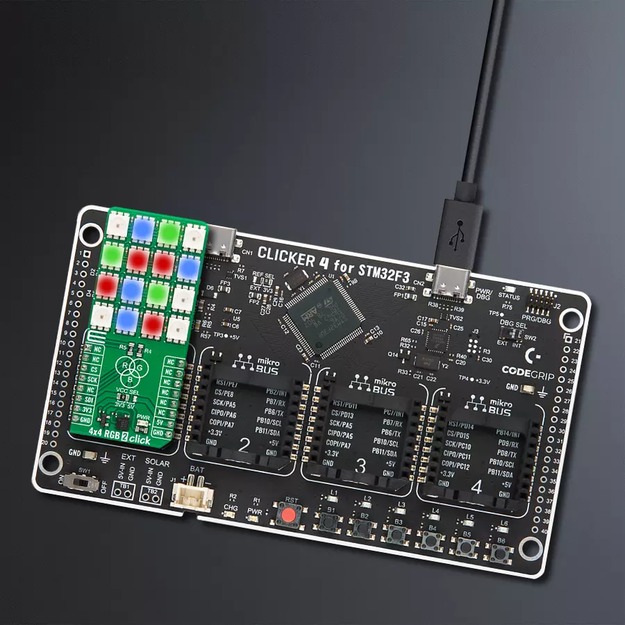
Clicker 4 for STM32F3 is a compact development board designed as a complete solution, you can use it to quickly build your own gadgets with unique functionalities. Featuring a STM32F302VCT6, four mikroBUS™ sockets for Click boards™ connectivity, power managment, and more, it represents a perfect solution for the rapid development of many different types of applications. At its core, there is a STM32F302VCT6 MCU, a powerful microcontroller by STMicroelectronics, based on the high-
performance Arm® Cortex®-M4 32-bit processor core operating at up to 168 MHz frequency. It provides sufficient processing power for the most demanding tasks, allowing Clicker 4 to adapt to any specific application requirements. Besides two 1x20 pin headers, four improved mikroBUS™ sockets represent the most distinctive connectivity feature, allowing access to a huge base of Click boards™, growing on a daily basis. Each section of Clicker 4 is clearly marked, offering an intuitive and clean interface. This makes working with the development
board much simpler and thus, faster. The usability of Clicker 4 doesn’t end with its ability to accelerate the prototyping and application development stages: it is designed as a complete solution which can be implemented directly into any project, with no additional hardware modifications required. Four mounting holes [4.2mm/0.165”] at all four corners allow simple installation by using mounting screws. For most applications, a nice stylish casing is all that is needed to turn the Clicker 4 development board into a fully functional, custom design.

Microcontroller Overview
MCU Card / MCU

Architecture
ARM Cortex-M4
MCU Memory (KB)
256
Silicon Vendor
STMicroelectronics
Pin count
100
RAM (Bytes)
40960
Used MCU Pins
mikroBUS™ mapper
Take a closer look
Click board™ Schematic
Step by step
Project assembly

Start by selecting your development board and Click board™. Begin with the CLICKER 4 for STM32F302VCT6 as your development board.


Track your results in real time
Application Output
1. Application Output - In Debug mode, the 'Application Output' window enables real-time data monitoring, offering direct insight into execution results. Ensure proper data display by configuring the environment correctly using the provided tutorial.

2. UART Terminal - Use the UART Terminal to monitor data transmission via a USB to UART converter, allowing direct communication between the Click board™ and your development system. Configure the baud rate and other serial settings according to your project's requirements to ensure proper functionality. For step-by-step setup instructions, refer to the provided tutorial.

3. Plot Output - The Plot feature offers a powerful way to visualize real-time sensor data, enabling trend analysis, debugging, and comparison of multiple data points. To set it up correctly, follow the provided tutorial, which includes a step-by-step example of using the Plot feature to display Click board™ readings. To use the Plot feature in your code, use the function: plot(*insert_graph_name*, variable_name);. This is a general format, and it is up to the user to replace 'insert_graph_name' with the actual graph name and 'variable_name' with the parameter to be displayed.

Software Support
Library Description
This library contains API for 4x4 RGB 2 Click driver.
Key functions:
c4x4rgb2_set_led_color- This function sets the color of the selected led in the led matrix.c4x4rgb2_set_led_brightness- This function sets the brightness of the selected led in the led matrix.c4x4rgb2_write_led_matrix- This function writes the led matrix data from the click context object.
Open Source
Code example
The complete application code and a ready-to-use project are available through the NECTO Studio Package Manager for direct installation in the NECTO Studio. The application code can also be found on the MIKROE GitHub account.
/*!
 * @file main.c
 * @brief 4x4 RGB 2 Click example
 *
 * # Description
 * This example demonstrates the use of 4x4 RGB 2 Click board by setting all 16 LEDs
 * to different colors and changing the LEDs color every 500 milliseconds.
 *
 * The demo application is composed of two sections :
 *
 * ## Application Init
 * Initializes the driver and performs the Click default configuration which sets
 * the LEDs brightness to level 1 and the color to black (all LEDs off).
 *
 * ## Application Task
 * Sets all 16 LEDs to a different colors and changes their color every 500 milliseconds.
 * All data is displayed on the USB UART where you can track their changes.
 *
 * @author Stefan Filipovic
 *
 */

#include "board.h"
#include "log.h"
#include "c4x4rgb2.h"

static c4x4rgb2_t c4x4rgb2;
static log_t logger;

static c4x4rgb2_color_t color[ C4X4RGB2_NUM_COLORS ] =
{
    { C4X4RGB2_COLOR_BLACK, "BLACK" },
    { C4X4RGB2_COLOR_WHITE, "WHITE" },
    { C4X4RGB2_COLOR_RED, "RED" },
    { C4X4RGB2_COLOR_LIME, "LIME" },
    { C4X4RGB2_COLOR_BLUE, "BLUE" },
    { C4X4RGB2_COLOR_YELLOW, "YELLOW" },
    { C4X4RGB2_COLOR_CYAN, "CYAN" },
    { C4X4RGB2_COLOR_MAGENTA, "MAGENTA" },
    { C4X4RGB2_COLOR_SILVER, "SILVER" },
    { C4X4RGB2_COLOR_GRAY, "GRAY" },
    { C4X4RGB2_COLOR_MAROON, "MAROON" },
    { C4X4RGB2_COLOR_OLIVE, "OLIVE" },
    { C4X4RGB2_COLOR_GREEN, "GREEN" },
    { C4X4RGB2_COLOR_PURPLE, "PURPLE" },
    { C4X4RGB2_COLOR_TEAL, "TEAL" },
    { C4X4RGB2_COLOR_NAVY, "NAVY" }
};

void application_init ( void )
{
    log_cfg_t log_cfg;  /**< Logger config object. */
    c4x4rgb2_cfg_t c4x4rgb2_cfg;  /**< Click config object. */

    /**
     * Logger initialization.
     * Default baud rate: 115200
     * Default log level: LOG_LEVEL_DEBUG
     * @note If USB_UART_RX and USB_UART_TX
     * are defined as HAL_PIN_NC, you will
     * need to define them manually for log to work.
     * See @b LOG_MAP_USB_UART macro definition for detailed explanation.
     */
    LOG_MAP_USB_UART( log_cfg );
    log_init( &logger, &log_cfg );
    log_info( &logger, " Application Init " );

    // Click initialization.
    c4x4rgb2_cfg_setup( &c4x4rgb2_cfg );
    C4X4RGB2_MAP_MIKROBUS( c4x4rgb2_cfg, MIKROBUS_1 );
    if ( SPI_MASTER_ERROR == c4x4rgb2_init( &c4x4rgb2, &c4x4rgb2_cfg ) )
    {
        log_error( &logger, " Communication init." );
        for ( ; ; );
    }

    if ( C4X4RGB2_ERROR == c4x4rgb2_default_cfg ( &c4x4rgb2 ) )
    {
        log_error( &logger, " Default configuration." );
        for ( ; ; );
    }

    log_info( &logger, " Application Task " );
}

void application_task ( void )
{
    static uint8_t color_num = 0;
    for ( uint8_t led_cnt = C4X4RGB2_LED_0; led_cnt <= C4X4RGB2_LED_15; led_cnt++ )
    {
        c4x4rgb2_set_led_color ( &c4x4rgb2, led_cnt,
                                 color[ ( led_cnt + color_num ) % C4X4RGB2_NUM_COLORS ].rgb );
        log_printf( &logger, " LED %u Color: %s - %.6LX\r\n", ( uint16_t ) led_cnt,
                    color[ ( led_cnt + color_num ) % C4X4RGB2_NUM_COLORS ].name,
                    color[ ( led_cnt + color_num ) % C4X4RGB2_NUM_COLORS ].rgb );
    }
    if ( C4X4RGB2_OK == c4x4rgb2_write_led_matrix ( &c4x4rgb2 ) )
    {
        log_printf( &logger, " Write LED Matrix\r\n\n" );
        Delay_ms ( 500 );
    }
    if ( ++color_num >= C4X4RGB2_NUM_COLORS )
    {
        color_num = 0;
    }
}

int main ( void )
{
    /* Do not remove this line or clock might not be set correctly. */
    #ifdef PREINIT_SUPPORTED
    preinit();
    #endif

    application_init( );

    for ( ; ; )
    {
        application_task( );
    }

    return 0;
}

// ------------------------------------------------------------------------ END
Additional Support
Resources
Category:LED Matrix