Optimize efficiency through digital VCP monitoring based on the INA260 and TM4C1294KCPDT
Your digital guide to current and power excellence!

Published Aug 11, 2023
Click board™
VCP Monitor Click
Dev. board
Fusion for Tiva v8
Compiler
NECTO Studio
MCU
TM4C1294KCPDT
From real-time diagnostics to performance optimization, the possibilities are endless
A
A
Hardware Overview
How does it work?
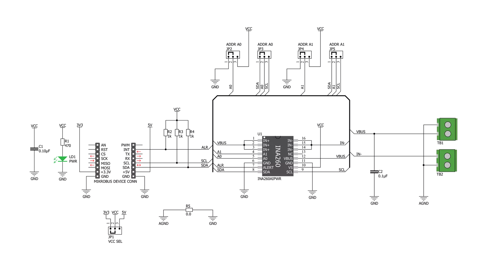
VCP Monitor Click is based on the INA260, a power monitor solution from Texas Instruments, which includes precision measurement of current, voltage, and power with low drift. The current-sensing resistor is designed as a 4-wire connected resistor that enables accurate measurements through a force-sense connection. The INA260 is internally calibrated to ensure the current-sensing resistor and amplifier are precisely matched. The INA260 device performs two measurements on the power supply bus. The current measurement on the LOAD connector is internally calculated by measuring the voltage developed across a known internal shunt resistor. The feature is a physical shunt resistance that can withstand current levels higher than the continuous handling limit of 15A without sustaining damage to the current-sensing resistor or the current-sensing amplifier if the excursions are brief. The voltage measurement on
the SUPPLY connector is calculated by measuring the voltage from the external VBUS pin to the ground. The voltage monitored ranges from 0V to 36V. The INA260 device performs two measurements on the power supply bus. The current measurement on the LOAD connector is internally calculated by measuring the voltage developed across a known internal shunt resistor, and the voltage measurement on the SUPPLY connector is calculated by measuring the voltage from the external VBUS pin to the ground. The VCP Monitor click is compatible with the I2C communication protocol. The INA260 has two slave address selection pins, A0 and A1. For I2C slave address selection, the VCP Monitor click has two cross-shape jumpers, first for set pin A0 and second for set A1 pin. One cross-shape jumper has four positions for the select address pins, which can be selected with an SMD 0 ohm resistor; the
address pin can be connected to GND, VS, SCL, or SDA pins. The VCP Monitor Clicks with the two separate jumpers on the Click board™ user can set the desired address. The INA260AIPWR provides the opportunity of the 16 possible different I2C addresses. The INA260AIPWR is supported with an ALERT pin connected to the INT pin on mikroBUS™ to interrupt the ongoing MCU routine in case of the alert condition. INT pin can be programmed to respond to a user-defined event or a conversion-ready notification. This Click board™ can operate with either 3.3V or 5V logic voltage levels selected via the VCC SEL jumper. This way, both 3.3V and 5V capable MCUs can use the communication lines properly. Also, this Click board™ comes equipped with a library containing easy-to-use functions and an example code that can be used, as a reference, for further development.


Features overview
Development board
Fusion for TIVA v8 is a development board specially designed for the needs of rapid development of embedded applications. It supports a wide range of microcontrollers, such as different 32-bit ARM® Cortex®-M based MCUs from Texas Instruments, regardless of their number of pins, and a broad set of unique functions, such as the first-ever embedded debugger/programmer over a WiFi network. The development board is well organized and designed so that the end-user has all the necessary elements, such as switches, buttons, indicators, connectors, and others, in one place. Thanks to innovative manufacturing technology, Fusion for TIVA v8 provides a fluid and immersive working experience, allowing access
anywhere and under any circumstances at any time. Each part of the Fusion for TIVA v8 development board contains the components necessary for the most efficient operation of the same board. An advanced integrated CODEGRIP programmer/debugger module offers many valuable programming/debugging options, including support for JTAG, SWD, and SWO Trace (Single Wire Output)), and seamless integration with the Mikroe software environment. Besides, it also includes a clean and regulated power supply module for the development board. It can use a wide range of external power sources, including a battery, an external 12V power supply, and a power source via the USB Type-C (USB-C) connector.
Communication options such as USB-UART, USB HOST/DEVICE, CAN (on the MCU card, if supported), and Ethernet is also included. In addition, it also has the well-established mikroBUS™ standard, a standardized socket for the MCU card (SiBRAIN standard), and two display options for the TFT board line of products and character-based LCD. Fusion for TIVA v8 is an integral part of the Mikroe ecosystem for rapid development. Natively supported by Mikroe software tools, it covers many aspects of prototyping and development thanks to a considerable number of different Click boards™ (over a thousand boards), the number of which is growing every day.

Microcontroller Overview
MCU Card / MCU
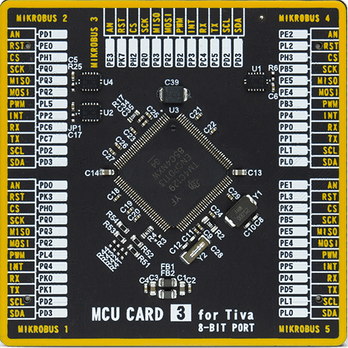
Type
8th Generation
Architecture
ARM Cortex-M4
MCU Memory (KB)
512
Silicon Vendor
Texas Instruments
Pin count
128
RAM (Bytes)
262144
Used MCU Pins
mikroBUS™ mapper
Take a closer look
Click board™ Schematic
Step by step
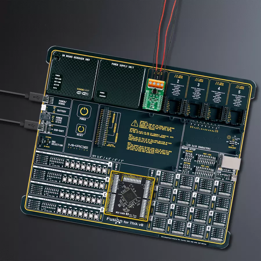
Project assembly

Start by selecting your development board and Click board™. Begin with the Fusion for Tiva v8 as your development board.


Track your results in real time
Application Output
1. Application Output - In Debug mode, the 'Application Output' window enables real-time data monitoring, offering direct insight into execution results. Ensure proper data display by configuring the environment correctly using the provided tutorial.

2. UART Terminal - Use the UART Terminal to monitor data transmission via a USB to UART converter, allowing direct communication between the Click board™ and your development system. Configure the baud rate and other serial settings according to your project's requirements to ensure proper functionality. For step-by-step setup instructions, refer to the provided tutorial.

3. Plot Output - The Plot feature offers a powerful way to visualize real-time sensor data, enabling trend analysis, debugging, and comparison of multiple data points. To set it up correctly, follow the provided tutorial, which includes a step-by-step example of using the Plot feature to display Click board™ readings. To use the Plot feature in your code, use the function: plot(*insert_graph_name*, variable_name);. This is a general format, and it is up to the user to replace 'insert_graph_name' with the actual graph name and 'variable_name' with the parameter to be displayed.

Software Support
Library Description
This library contains API for VCP Monitor Click driver.
Key functions:
vcpmonitor_get_current- This function reads current data in mAvcpmonitor_get_power- This function reads power data in mWvcpmonitor_get_voltage- This function reads voltage data in mV.
Open Source
Code example
The complete application code and a ready-to-use project are available through the NECTO Studio Package Manager for direct installation in the NECTO Studio. The application code can also be found on the MIKROE GitHub account.
/*!
 * \file
 * \brief VCPmonitor Click example
 *
 * # Description
 * The VCP Monitor Click is add-on board power monitor system. This Click board is
 * based on precision digital current and power monitor with low-drift, integrated
 * precision shunt resistor.
 *
 * The demo application is composed of two sections :
 *
 * ## Application Init
 * Initiaizes the driver, and checks the communication by reading the device and manufacture IDs.
 * After that, performs the device default configuration.
 *
 * ## Application Task
 * Displays the voltage, current, and power measured by the sensor on the USB UART every 2 seconds.
 *
 * \author MikroE Team
 *
 */
// ------------------------------------------------------------------- INCLUDES

#include "board.h"
#include "log.h"
#include "vcpmonitor.h"

// ------------------------------------------------------------------ VARIABLES

static vcpmonitor_t vcpmonitor;
static log_t logger;
static uint16_t manufacture_id;
static uint16_t did_id;

// ------------------------------------------------------ APPLICATION FUNCTIONS

void application_init ( void )
{
    log_cfg_t log_cfg;
    vcpmonitor_cfg_t cfg;

    /**
     * Logger initialization.
     * Default baud rate: 115200
     * Default log level: LOG_LEVEL_DEBUG
     * @note If USB_UART_RX and USB_UART_TX
     * are defined as HAL_PIN_NC, you will
     * need to define them manually for log to work.
     * See @b LOG_MAP_USB_UART macro definition for detailed explanation.
     */
    LOG_MAP_USB_UART( log_cfg );
    log_init( &logger, &log_cfg );
    log_info( &logger, "---- Application Init ----" );

    vcpmonitor_cfg_setup( &cfg );
    VCPMONITOR_MAP_MIKROBUS( cfg, MIKROBUS_1 );
    vcpmonitor_init( &vcpmonitor, &cfg );

    if ( VCPMONITOR_OK == vcpmonitor_get_id_value( &vcpmonitor, &manufacture_id, &did_id ) )
    {
        log_printf( &logger, ">> Manufacture ID: 0x%.4X\r\n", manufacture_id );
        log_printf( &logger, ">> Device ID: 0x%.4X\r\n", did_id );
    }
    else
    {
        log_error( &logger, " WRONG ID READ! " );
        log_printf( &logger, "Please restart your system.\r\n" );
        for ( ; ; );
    }

    vcpmonitor_default_cfg(&vcpmonitor );
    Delay_ms ( 500 );
}

void application_task ( void )
{
    float current_data;
    float voltage_data;
    float power_data;

    current_data = vcpmonitor_get_current( &vcpmonitor );
    log_printf( &logger, ">> Current : %.2f mA\r\n", current_data );

    voltage_data = vcpmonitor_get_voltage( &vcpmonitor );
    log_printf( &logger, ">> Voltage : %.2f mV\r\n", voltage_data );

    power_data = vcpmonitor_get_power( &vcpmonitor );
    log_printf( &logger, ">> Power : %.2f mW\r\n", power_data );

    log_printf( &logger, "-------------------------------\r\n" );
    Delay_ms ( 1000 );
    Delay_ms ( 1000 );
}

int main ( void )
{
    /* Do not remove this line or clock might not be set correctly. */
    #ifdef PREINIT_SUPPORTED
    preinit();
    #endif

    application_init( );

    for ( ; ; )
    {
        application_task( );
    }

    return 0;
}


// ------------------------------------------------------------------------ END


