Redefine how you sense and measure inductance with LDC1041 and STM32L496AG
Infinite possibilities, one converter: Inductance-to-Digital marvel!
Published Jul 22, 2025
Click board™
LDC 2 Click
Dev. board
Discovery kit with STM32L496AG MCU
Compiler
NECTO Studio
MCU
STM32L496AG
Elevate your measurement capabilities with our inductance-to-digital converter, an essential tool for engineers and researchers seeking high-precision sensing in fields like robotics, instrumentation, and materials science
A
A
Hardware Overview
How does it work?
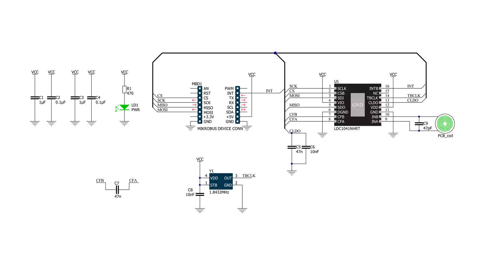
LDC 2 Click is based on the LDC1041, an inductance-to-digital converter simultaneously measuring an LC resonator's impedance and resonant frequency from Texas Instruments. This Click board™ is easy to use, requiring only the sensor frequency within 5kHz and 5MHz to begin sensing, and demonstrates the use of inductive sensing technology to sense and measure a conductive target object's presence, position, or composition. In addition, the LDC1041 also measures the oscillation frequency of the LC circuit, which is used to determine the inductance of the LC circuit. The device then outputs a digital value that is inversely proportional to frequency. The LDC measures the inductance change that a conductive target causes when it moves into the inductor's AC magnetic field to provide information about the target's position over a
sensor coil. The inductance shift is caused by eddy currents (circulating currents) generated in the target due to the sensor's magnetic field. These eddy currents generate a secondary magnetic field that opposes the sensor field, causing a shift in the observed inductance, used for precise positioning of the target as it moves laterally over the sensor coil. Also, the LDC1041 has two power modes: Active and Standby Mode. Active Mode enables proximity data and frequency data conversion, while Standby mode represents the default mode on the devices' Power-Up sequence. In Standby Mode, the conversion process is disabled. This Click board™ comes with an example of a PCB sensor coil designed to give the user maximum flexibility. The LDC1041 communicates with MCU using the standard SPI serial interface with a maximum frequency of
4MHz. In addition to this serial interface, one GPIO pin connected to the mikroBUS™ socket is also used. The configurable interrupt pin routed to the INT pin of the mikroBUS™ socket may be configured in three different ways by programming the interrupt Terminal mode register with SPI. An interrupt pin can act as a proximity switch, wake-up feature, or data-ready pin, indicating a valid condition for new data availability. This Click board™ can be operated only with a 5V logic voltage level. The board must perform appropriate logic voltage level conversion before using MCUs with different logic levels. Also, it comes equipped with a library containing functions and an example code that can be used as a reference for further development.


Features overview
Development board
The 32L496GDISCOVERY Discovery kit serves as a comprehensive demonstration and development platform for the STM32L496AG microcontroller, featuring an Arm® Cortex®-M4 core. Designed for applications that demand a balance of high performance, advanced graphics, and ultra-low power consumption, this kit enables seamless prototyping for a wide range of embedded solutions. With its innovative energy-efficient
architecture, the STM32L496AG integrates extended RAM and the Chrom-ART Accelerator, enhancing graphics performance while maintaining low power consumption. This makes the kit particularly well-suited for applications involving audio processing, graphical user interfaces, and real-time data acquisition, where energy efficiency is a key requirement. For ease of development, the board includes an onboard ST-LINK/V2-1
debugger/programmer, providing a seamless out-of-the-box experience for loading, debugging, and testing applications without requiring additional hardware. The combination of low power features, enhanced memory capabilities, and built-in debugging tools makes the 32L496GDISCOVERY kit an ideal choice for prototyping advanced embedded systems with state-of-the-art energy efficiency.

Microcontroller Overview
MCU Card / MCU

Architecture
ARM Cortex-M4
MCU Memory (KB)
1024
Silicon Vendor
STMicroelectronics
Pin count
169
RAM (Bytes)
327680
Used MCU Pins
mikroBUS™ mapper
Take a closer look
Click board™ Schematic
Step by step
Project assembly

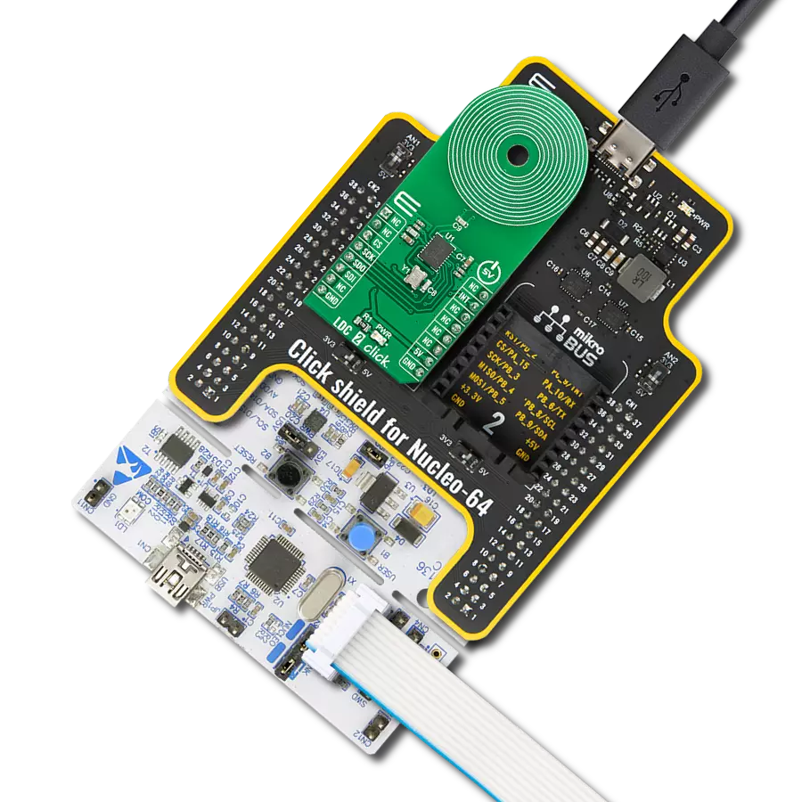
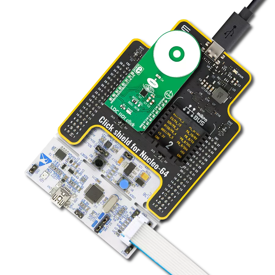
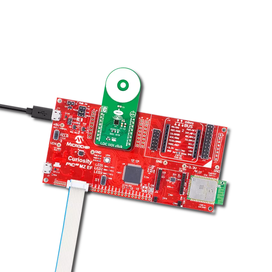
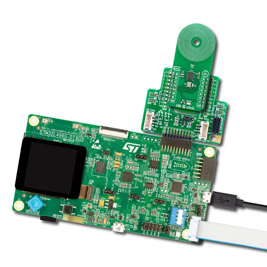
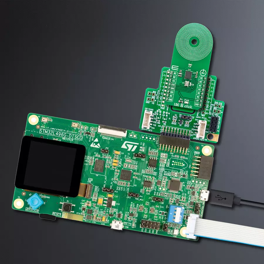
Start by selecting your development board and Click board™. Begin with the Discovery kit with STM32L496AG MCU as your development board.


Software Support
Library Description
This library contains API for LDC 2 Click driver.
Key functions:
ldc2_measure_resonance_impedance- This function measures the resonance impedance and proximity dataldc2_measure_inductance- This function measures the inductance and sensor frequencyldc2_get_sensor_frequency- This function reads and calculates the sensor frequency.
Open Source
Code example
The complete application code and a ready-to-use project are available through the NECTO Studio Package Manager for direct installation in the NECTO Studio. The application code can also be found on the MIKROE GitHub account.
/*!
 * @file main.c
 * @brief LDC2 Click example
 *
 * # Description
 * This example demonstrates the use of LDC 2 Click board.
 *
 * The demo application is composed of two sections :
 *
 * ## Application Init
 * Initializes the driver and configures the Click board.
 *
 * ## Application Task
 * Measures the resonance impedance and proximity as well as the inductance and sensor frequency
 * approximately every 200ms and displays all values on the USB UART.
 *
 * @author Stefan Filipovic
 *
 */

#include "board.h"
#include "log.h"
#include "ldc2.h"

static ldc2_t ldc2;
static log_t logger;

void application_init ( void )
{
    log_cfg_t log_cfg;      /**< Logger config object. */
    ldc2_cfg_t ldc2_cfg;    /**< Click config object. */

    /**
     * Logger initialization.
     * Default baud rate: 115200
     * Default log level: LOG_LEVEL_DEBUG
     * @note If USB_UART_RX and USB_UART_TX
     * are defined as HAL_PIN_NC, you will
     * need to define them manually for log to work.
     * See @b LOG_MAP_USB_UART macro definition for detailed explanation.
     */
    LOG_MAP_USB_UART( log_cfg );
    log_init( &logger, &log_cfg );
    Delay_ms ( 100 );
    log_info( &logger, " Application Init " );

    // Click initialization.

    ldc2_cfg_setup( &ldc2_cfg );
    LDC2_MAP_MIKROBUS( ldc2_cfg, MIKROBUS_1 );
    if ( SPI_MASTER_ERROR == ldc2_init( &ldc2, &ldc2_cfg ) )
    {
        log_error( &logger, " Application Init Error. " );
        log_info( &logger, " Please, run program again... " );

        for ( ; ; );
    }

    if ( LDC2_ERROR == ldc2_default_cfg ( &ldc2 ) )
    {
        log_error( &logger, " Default Config Error. " );
        log_info( &logger, " Please, run program again... " );

        for ( ; ; );
    }
    log_info( &logger, " Application Task " );
}

void application_task ( void )
{
    uint8_t prox_data = 0;
    float rp_data = 0;
    float freq = 0;
    float inductance = 0;

    if ( LDC2_OK == ldc2_measure_resonance_impedance( &ldc2, &prox_data, &rp_data ) )
    {
        log_printf( &logger, " Proximity: %u\r\n Resonance Impedance: %.3f kOhm\r\n\n", ( uint16_t ) prox_data, rp_data );
    }

    if ( LDC2_OK == ldc2_measure_inductance( &ldc2, &freq, &inductance ) )
    {
        log_printf( &logger, " Sensor Frequency: %.3f MHz\r\n Inductance: %.6f uH\r\n\n", freq, inductance );
    }

    Delay_ms ( 200 );
}

int main ( void )
{
    /* Do not remove this line or clock might not be set correctly. */
    #ifdef PREINIT_SUPPORTED
    preinit();
    #endif

    application_init( );

    for ( ; ; )
    {
        application_task( );
    }

    return 0;
}

// ------------------------------------------------------------------------ END
Additional Support
Resources
Category:Inductance