Present textual information, numbers, and basic graphics with LS013B7DH03 and TM4C129ENCPDT
Customization made easy: Monochrome LCD at your command!
Published Sep 04, 2023
Click board™
LCD Mono Click
Dev. board
Fusion for Tiva v8
Compiler
NECTO Studio
MCU
TM4C129ENCPDT
Tailor the displayed information to your specific application, whether it's showing real-time data, status indicators, alerts, or user instructions.
A
A
Hardware Overview
How does it work?
LCD Mono Click is based on the LS013B7DH03, an LCD display from Sharp that has a reflective active-matrix with a slightly transmissive-type memory liquid crystal display module with a 128 x128 panel which uses CG silicon thin film transistor. Its transmissive mode is implemented with a backlight, and you can control the display with serial data signal communication. It features a thin, light, and compact module with monolithic technology, and its most important feature is the super low power consumption TFT panel. For an MCU application, a powerful display can often be off-limits because of price, CPU processing power, or power budget. However, you can create a powerful display application using the EFM32's energy-saving capabilities and a Sharp low-power matrix memory LCD. The application can drive a
128x128 pixel display drawing as little as 2 µA while showing a static image. Even when updating the frame every second, the current consumption can be lower than 5µA. The display for this click, the LS013B7DH03 LCD, is a 1.28", 128x128 pixels monochrome display with a 3-wire SPI interface. Apart from the SPI interface, the display requires a 3.3V power supply and three extra pins named EXTMODE, EXTCOMIN, and DISP. The EXTMODE pin controls how polarity inversion is controlled. The display requires that the polarity across the Liquid Crystal Cell is reversed at a constant frequency. This polarity inversion prevents charge from building up within the cell. If EXTMODE is LOW, the polarity inversion is toggled by sending a special command over SPI. If it is HIGH, polarity inversion is controlled by the EXTCOMIN pin.
If EXTMODE is HIGH, the polarity inversion is armed for every rising edge of the EXTCOMIN pin. The actual polarity inversion is triggered at the next transition of SCS. The toggling frequency should be at least 1 Hz. If EXTMODE is LOW, this pin is ignored. The DISP pin toggles the display on or off (without the pixels losing their state). When LOW, the display is off; when HIGH, the display is on. This Click board™ can be operated only with a 3.3V logic voltage level. The board must perform appropriate logic voltage level conversion before using MCUs with different logic levels. Also, it comes equipped with a library containing functions and an example code that can be used as a reference for further development.


Features overview
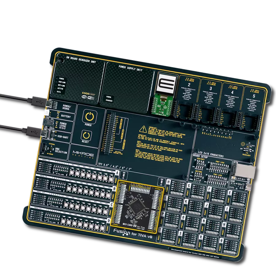
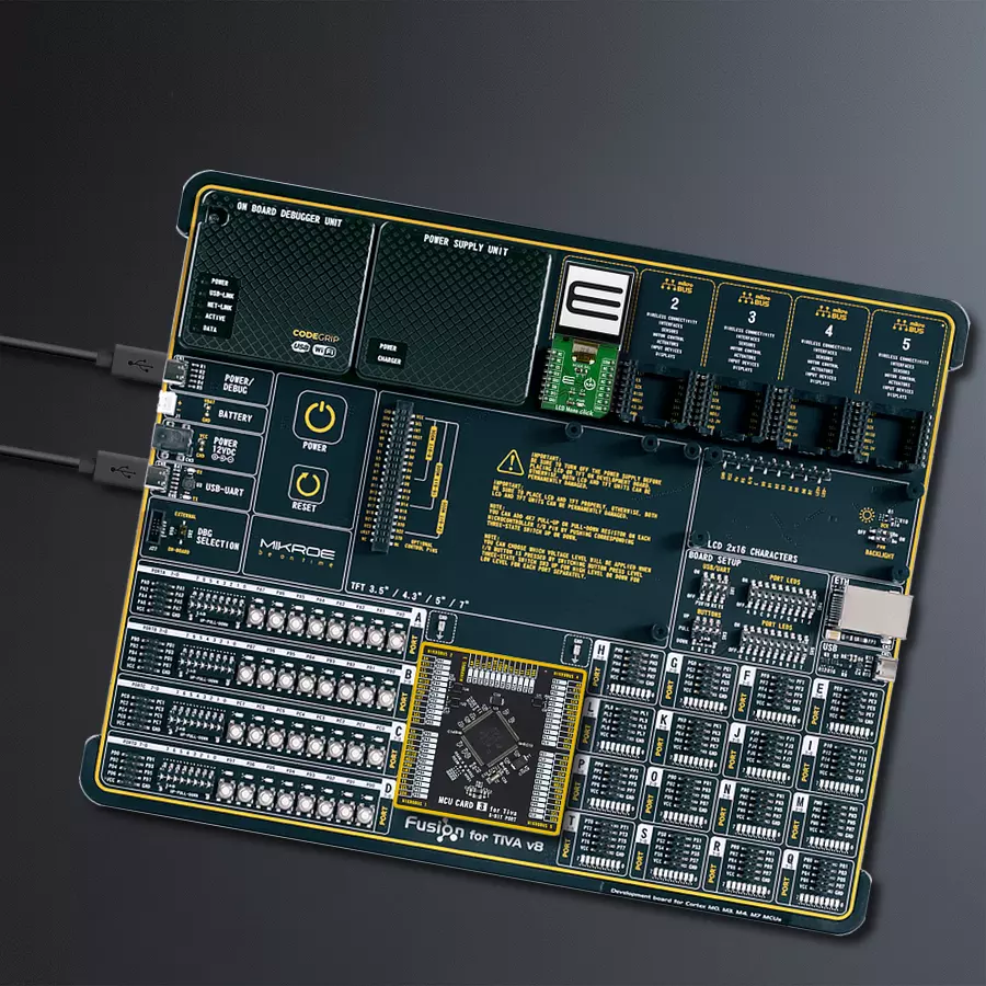
Development board
Fusion for TIVA v8 is a development board specially designed for the needs of rapid development of embedded applications. It supports a wide range of microcontrollers, such as different 32-bit ARM® Cortex®-M based MCUs from Texas Instruments, regardless of their number of pins, and a broad set of unique functions, such as the first-ever embedded debugger/programmer over a WiFi network. The development board is well organized and designed so that the end-user has all the necessary elements, such as switches, buttons, indicators, connectors, and others, in one place. Thanks to innovative manufacturing technology, Fusion for TIVA v8 provides a fluid and immersive working experience, allowing access
anywhere and under any circumstances at any time. Each part of the Fusion for TIVA v8 development board contains the components necessary for the most efficient operation of the same board. An advanced integrated CODEGRIP programmer/debugger module offers many valuable programming/debugging options, including support for JTAG, SWD, and SWO Trace (Single Wire Output)), and seamless integration with the Mikroe software environment. Besides, it also includes a clean and regulated power supply module for the development board. It can use a wide range of external power sources, including a battery, an external 12V power supply, and a power source via the USB Type-C (USB-C) connector.
Communication options such as USB-UART, USB HOST/DEVICE, CAN (on the MCU card, if supported), and Ethernet is also included. In addition, it also has the well-established mikroBUS™ standard, a standardized socket for the MCU card (SiBRAIN standard), and two display options for the TFT board line of products and character-based LCD. Fusion for TIVA v8 is an integral part of the Mikroe ecosystem for rapid development. Natively supported by Mikroe software tools, it covers many aspects of prototyping and development thanks to a considerable number of different Click boards™ (over a thousand boards), the number of which is growing every day.

Microcontroller Overview
MCU Card / MCU

Type
8th Generation
Architecture
ARM Cortex-M4
MCU Memory (KB)
1024
Silicon Vendor
Texas Instruments
Pin count
128
RAM (Bytes)
262144
Used MCU Pins
mikroBUS™ mapper
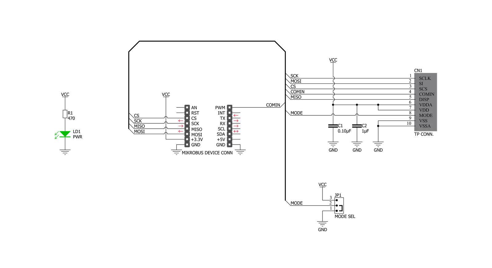
Take a closer look
Click board™ Schematic
Step by step
Project assembly

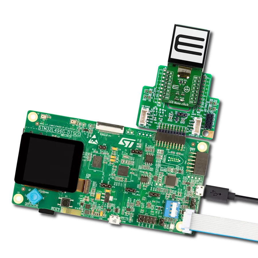
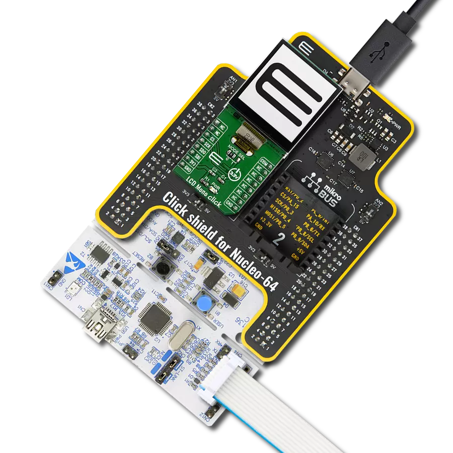
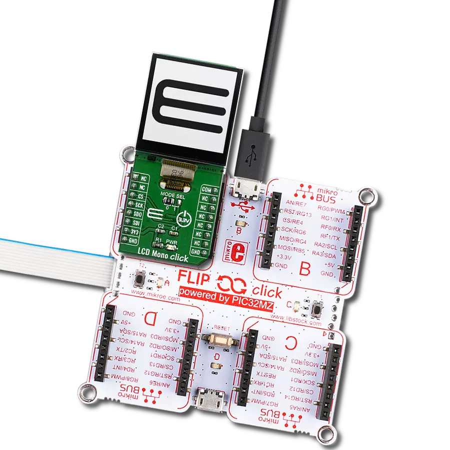
Start by selecting your development board and Click board™. Begin with the Fusion for Tiva v8 as your development board.


Software Support
Library Description
This library contains API for LCD Mono Click driver.
Key functions:
lcdmono_draw_text- Draw text on the screenlcdmono_display_power- Display Power Statelcdmono_display_reset- Reset procedure
Open Source
Code example
The complete application code and a ready-to-use project are available through the NECTO Studio Package Manager for direct installation in the NECTO Studio. The application code can also be found on the MIKROE GitHub account.
/*!
 * \file
 * \brief LcdMono Click example
 *
 * # Description
 * This application sets text on lcd displey.
 *
 * The demo application is composed of two sections :
 *
 * ## Application Init
 * Driver initialization - Starting LCD Mono display. Print text to the display by changing font size ...
 *
 * ## Application Task
 * Drawing an image to the display every 3 second.
 *
 * *note:*
 * - Create Image:
 *     Save the image in resolution of 128x128 px with the extension (monochrome bmp) ...
 *     Upload the image to Image2Lcd program
 *     Set parameters to:
 *            1. Output file type : C array
 *            2. Scan Mode : Horisontal scan
 *            3. Bits Pixel : monochrome
 *            4. Max width and height : 128x128
 *            5. Check only MSB first
 *            6. Check Reverse color and adjust Normal type
 * The image to be generated should contain about 2048 bytes ...
 * Insert the image into the file lcdmono_image.h
 *
 * - Create Font:
 *     Close existing project, open a new VTFT project
 *     Add label and adjust text font
 *     Generate source code
 *     Copy the font from resource.c file to this project in file lcdmono_font.h
 *
 * \author Nemanja Medakovic
 *
 */
// ------------------------------------------------------------------- INCLUDES

#include "board.h"
#include "log.h"
#include "lcdmono.h"
#include "lcdmono_font.h"
#include "lcdmono_image.h"

// ------------------------------------------------------------------ VARIABLES

static lcdmono_t lcdmono;

static const char demo_text_lcd[ 4 ] = { 'L', 'C', 'D', 0 };
static const char demo_text_mono[ 5 ] = { 'M', 'o', 'n', 'o', 0 };
static const char demo_text_128x128px[ 10 ] = { '1', '2', '8', 'x', '1', '2', '8', 'p', 'x', 0 };

// ------------------------------------------------------ APPLICATION FUNCTIONS

void application_init ( void )
{
    lcdmono_cfg_t cfg;
    lcdmono_text_settings_t tx_set;
    lcdmono_font_t font_cfg;

    //  Click initialization.
    lcdmono_cfg_setup( &cfg );
    LCDMONO_MAP_MIKROBUS( cfg, MIKROBUS_1 );
    lcdmono_init( &lcdmono, &cfg );

    lcdmono_display_reset( &lcdmono );
    lcdmono_clear( &lcdmono );

    // Background color for all text
    tx_set.bg_color = LCDMONO_COLOR_WHITE;
    // Display text
    font_cfg.this_font = lcdmono_font_tahoma_16;
    lcdmono_set_font( &lcdmono, &font_cfg );

    tx_set.len = 3;
    tx_set.start_cord_x = 25;
    tx_set.start_cord_y = 15;
    lcdmono_draw_text( &lcdmono, demo_text_lcd, &tx_set, LCDMONO_REFRESH_TEXT_BUFFER |
                                                         LCDMONO_CHECK_NEW_TEXT );

    font_cfg.this_font = lcdmono_font_tahoma_8;
    lcdmono_set_font( &lcdmono, &font_cfg );

    tx_set.len = 4;
    tx_set.start_cord_x = 60;
    tx_set.start_cord_y = 50;
    lcdmono_draw_text( &lcdmono, demo_text_mono, &tx_set, LCDMONO_CHECK_NEW_TEXT );

    tx_set.len = 9;
    tx_set.start_cord_x = 10;
    tx_set.start_cord_y = 80;
    lcdmono_draw_text( &lcdmono, demo_text_128x128px, &tx_set, LCDMONO_REFRESH_DISPLAY_END );

    Delay_ms ( 1000 );
    Delay_ms ( 1000 );
    Delay_ms ( 1000 );
    Delay_ms ( 1000 );
    Delay_ms ( 1000 );
    lcdmono_clear( &lcdmono );
}

void application_task ( void )
{
    lcdmono_draw_frame( &lcdmono, demo_img_mikroe_light );
    Delay_ms ( 1000 );
    Delay_ms ( 1000 );
    Delay_ms ( 1000 );
    lcdmono_draw_frame( &lcdmono, demo_img_mikroe );
    Delay_ms ( 1000 );
    Delay_ms ( 1000 );
    Delay_ms ( 1000 );
    lcdmono_draw_frame( &lcdmono, demo_img_logo_light );
    Delay_ms ( 1000 );
    Delay_ms ( 1000 );
    Delay_ms ( 1000 );
    lcdmono_draw_frame( &lcdmono, demo_img_logo );
    Delay_ms ( 1000 );
    Delay_ms ( 1000 );
    Delay_ms ( 1000 );
}

int main ( void )
{
    /* Do not remove this line or clock might not be set correctly. */
    #ifdef PREINIT_SUPPORTED
    preinit();
    #endif

    application_init( );

    for ( ; ; )
    {
        application_task( );
    }

    return 0;
}

// ------------------------------------------------------------------------ END