Increase your voltage with LT1945 and PIC32MZ2048EFM100
Boosted energy = increased potential

Published Jul 22, 2025
Click board™
Boost 8 Click
Dev. board
Curiosity PIC32 MZ EF
Compiler
NECTO Studio
MCU
PIC32MZ2048EFM100
Upgrade your power management and take your engineering game to the next level with a boost converter
A
A
Hardware Overview
How does it work?
Boost 8 Click is based on the LT1945, a dual micropower DC/DC converter from Analog Devices that boosts an input voltage to a higher level required by an output load. The LT1945 uses a constant off-time control scheme to provide high efficiency over a wide range of output currents. Each converter inside the LT1945 is designed with a 350mA current limit generating well-regulated positive and negative outputs of ±12V or ±24V, making the LT1945 ideal for various applications. It also contains additional circuitry to provide protection during the Start-Up sequence and under short-circuit conditions, reducing the average inductor output current and minimizing the
power dissipation in the power switch.As mentioned, the LT1945 can configure the positive and negative output voltage in the ±12V or ±24V range. The desired output voltage can be selected by positioning SMD jumpers labeled +VOUT SEL and -VOUT SEL to an appropriate position. It is also possible to control the activity of the output channels via two mikroBUS™ pins, EN+ and EN- pins routed to the RST and PWM pin of the mikroBUS™ socket. By setting these pins to a high logic state, the converter outputs are set to an active state, and regulated voltages are available at the output terminals. In the same way, setting these pins to a low logic level disables the channels.
This Click board™ can only be operated from a 3.3V logic voltage level. Therefore, the board must perform appropriate logic voltage level conversion before using MCUs with different logic levels. Additionally, there is a possibility for the LT1945 power supply selection via jumper labeled as VIN SEL to supply the LT1945 from an external power supply terminal in the range from 2.7V to 5V or with 3.3V from mikroBUS™ power rail. However, the Click board™ comes equipped with a library containing easy-to-use functions and an example code that can be used, as a reference, for further development.

Features overview
Development board
Curiosity PIC32 MZ EF development board is a fully integrated 32-bit development platform featuring the high-performance PIC32MZ EF Series (PIC32MZ2048EFM) that has a 2MB Flash, 512KB RAM, integrated FPU, Crypto accelerator, and excellent connectivity options. It includes an integrated programmer and debugger, requiring no additional hardware. Users can expand
functionality through MIKROE mikroBUS™ Click™ adapter boards, add Ethernet connectivity with the Microchip PHY daughter board, add WiFi connectivity capability using the Microchip expansions boards, and add audio input and output capability with Microchip audio daughter boards. These boards are fully integrated into PIC32’s powerful software framework, MPLAB Harmony,
which provides a flexible and modular interface to application development a rich set of inter-operable software stacks (TCP-IP, USB), and easy-to-use features. The Curiosity PIC32 MZ EF development board offers expansion capabilities making it an excellent choice for a rapid prototyping board in Connectivity, IOT, and general-purpose applications.

Microcontroller Overview
MCU Card / MCU

Architecture
PIC32
MCU Memory (KB)
2048
Silicon Vendor
Microchip
Pin count
100
RAM (Bytes)
524288
Used MCU Pins
mikroBUS™ mapper
Take a closer look
Click board™ Schematic

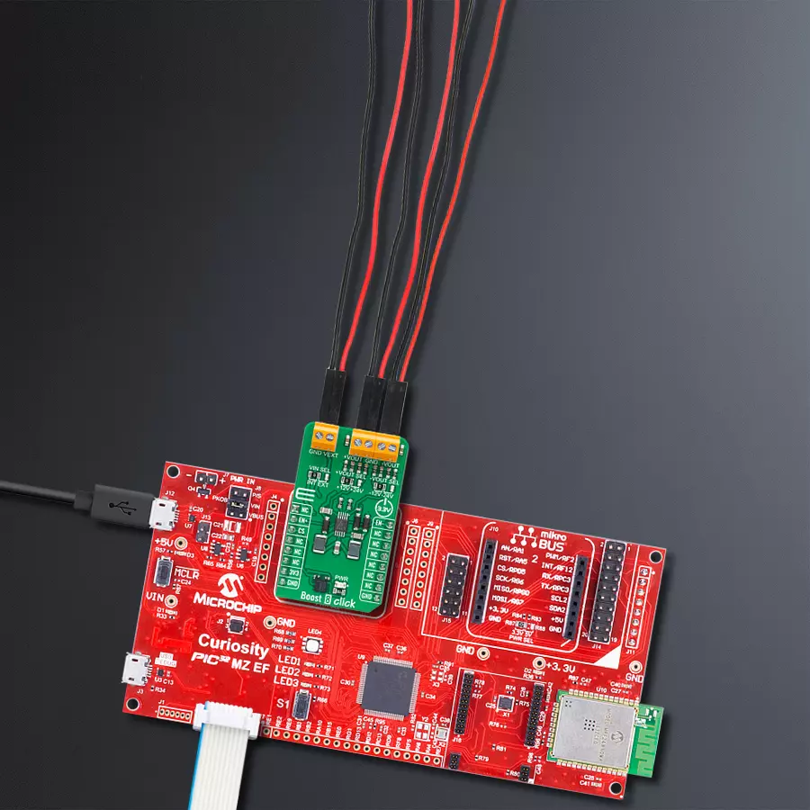
Step by step
Project assembly

Start by selecting your development board and Click board™. Begin with the Curiosity PIC32 MZ EF as your development board.


Software Support
Library Description
This library contains API for Boost 8 Click driver.
Key functions:
boost8_enable_positive_voltageEnable positive voltage output function.boost8_disable_positive_voltageDisable positive voltage output function.boost8_enable_negative_voltageEnable negative voltage output function.
Open Source
Code example
The complete application code and a ready-to-use project are available through the NECTO Studio Package Manager for direct installation in the NECTO Studio. The application code can also be found on the MIKROE GitHub account.
/*!
 * @file main.c
 * @brief Boost 8 Click Example.
 *
 * # Description
 * This is an example that demonstrates the use of the Boost 8 Click board.
 *
 * The demo application is composed of two sections :
 *
 * ## Application Init
 * Initializes EN+ and EN- pins, UART log, and performs default configuration.
 *
 * ## Application Task
 * Waits for user input in order to determine what output should be enabled.
 *
 * @author Stefan Ilic
 *
 */

#include "board.h"
#include "log.h"
#include "boost8.h"

static boost8_t boost8;   /**< Boost 8 Click driver object. */
static log_t logger;    /**< Logger object. */

/**
 * @brief Boost 8 log list of commands.
 * @details This function is used for logging a list of available commands used in this example.
 */
void boost8_list_of_commands( void );

void application_init ( void )
{
    log_cfg_t log_cfg;  /**< Logger config object. */
    boost8_cfg_t boost8_cfg;  /**< Click config object. */

    /**
     * Logger initialization.
     * Default baud rate: 115200
     * Default log level: LOG_LEVEL_DEBUG
     * @note If USB_UART_RX and USB_UART_TX
     * are defined as HAL_PIN_NC, you will
     * need to define them manually for log to work.
     * See @b LOG_MAP_USB_UART macro definition for detailed explanation.
     */
    LOG_MAP_USB_UART( log_cfg );
    log_init( &logger, &log_cfg );
    log_info( &logger, " Application Init " );

    // Click initialization.
    boost8_cfg_setup( &boost8_cfg );
    BOOST8_MAP_MIKROBUS( boost8_cfg, MIKROBUS_1 );
    if ( DIGITAL_OUT_UNSUPPORTED_PIN == boost8_init( &boost8, &boost8_cfg ) )
    {
        log_error( &logger, " Communication init." );
        for ( ; ; );
    }

    boost8_default_cfg ( &boost8 );

    log_info( &logger, " Application Task " );
    boost8_list_of_commands();
}

void application_task ( void )
{
    char inx;

    // Waiting for the user input and performing actions based on a selected command.
    if ( log_read( &logger, &inx, 1 ) != BOOST8_ERROR )
    {
        switch(inx)
        {
            case '1' :
            {
                log_printf( &logger, "Turning on positive output \r\n" );
                boost8_enable_positive_voltage( &boost8 );
                break;
            }
            case '2' :
            {
                log_printf( &logger, "Turning off positive output \r\n" );
                boost8_disable_positive_voltage( &boost8 );
                break;
            }
            case '3' :
            {
                log_printf( &logger, "Turning on negative output \r\n" );
                boost8_enable_negative_voltage( &boost8 );
                break;
            }
            case '4':
            {
                log_printf( &logger, "Turning off negative output \r\n" );
                boost8_disable_negative_voltage( &boost8 );
                break;
            }
            case '5' :
            {
                log_printf( &logger, "Turning on both outputs \r\n" );
                boost8_enable_both_outputs( &boost8 );
                break;
            }
            case '6' :
            {
                log_printf( &logger, "Turning off both outputs \r\n" );
                boost8_disable_both_outputs( &boost8 );
                break;
            }
            default:
            {
                log_printf( &logger, "> Invalid command \r\n" );
                boost8_list_of_commands();
                break;
            }
        }
    }

}

int main ( void )
{
    /* Do not remove this line or clock might not be set correctly. */
    #ifdef PREINIT_SUPPORTED
    preinit();
    #endif

    application_init( );

    for ( ; ; )
    {
        application_task( );
    }

    return 0;
}

void boost8_list_of_commands( void )
{
    log_printf( &logger, "> List of valid commands: \r\n" );
    log_printf( &logger, "1 - Turn on positive output \r\n" );
    log_printf( &logger, "2 - Turn off positive output \r\n" );
    log_printf( &logger, "3 - Turn on negative output \r\n" );
    log_printf( &logger, "4 - Turn off negative output \r\n" );
    log_printf( &logger, "5 - Turn on both outputs \r\n" );
    log_printf( &logger, "6 - Turn off both outputs \r\n" );
    log_printf( &logger, "Enter command from provided list:  \r\n" );
}

// ------------------------------------------------------------------------ END
Additional Support
Resources
Category:Boost


