Boost your power with MCP1642B and PIC18F57Q43
Experience the power of a voltage booster

Published Feb 13, 2024
Click board™
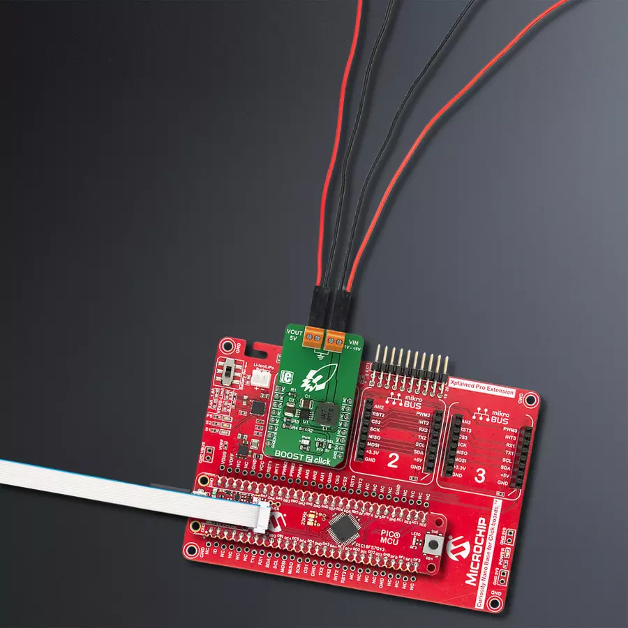
Boost 2 Click
Dev. board
Curiosity Nano with PIC18F57Q43
Compiler
NECTO Studio
MCU
PIC18F57Q43
Unlock maximum performance with our low-voltage synchronous boost regulator
A
A
Hardware Overview
How does it work?
Boost 2 Click is based on the MCP1642B, a 1 MHz low-voltage start-up synchronous boost regulator from Microchip. This IC is targeted towards boosting the voltage from NiCd, NiMH, and Li-Po/Li-Ion batteries, and as such, it has a great efficiency factor that allows for prolonged battery life. The MCP1642B uses the fixed switching frequency of 1MHz and has overcurrent and overtemperature protection to ensure safe operation. The voltage step-up process starts with the input voltage as low as 0.9V. Once the regulation is established, the input voltage can drop to even 0.5V, keeping the required regulated voltage at the output. The device should be powered with at least 1.8V at the input terminal for optimal efficiency. Output current depends on the input voltage - when powered with 3.3V at the
input, Boost 2 Click will be able to deliver about 800mA to the connected load. The device has no under-voltage protection limit, so it will boost the voltage when the input voltage reaches 0.9V. As with most step-up regulators, the input voltage should always be less than the voltage at the output to maintain the proper regulation. The MCP1642B step-up regulator actively damps the oscillations typically found at the switch node of a boost converter. This removes the high-frequency radiated noise, ensuring low-noise operation. The device also features the power good status pin, which is constructed as the open-drain output pulled HIGH by the onboard 10K resistor. This allows easy interfacing with the MCU. When the regulated output reaches 90% of its regulation, this pin will be pulled low, indicating
the power-good status. This pin is routed to the mikroBUS™ INT pin. Besides the power good status pin, the EN pin used to enable the device is routed to the mikroBUS™ CS pin. When pulled LOW, this pin will engage the true disconnect of the output load option, resulting in low quintessential currents suitable for battery-operated devices. This pin is also pulled HIGH by the onboard resistor. This Click board™ can operate with either 3.3V or 5V logic voltage levels selected via the LOGIC SEL jumper. This way, both 3.3V and 5V capable MCUs can use the communication lines properly. However, the Click board™ comes equipped with a library containing easy-to-use functions and an example code that can be used, as a reference, for further development.

Features overview
Development board
PIC18F57Q43 Curiosity Nano evaluation kit is a cutting-edge hardware platform designed to evaluate microcontrollers within the PIC18-Q43 family. Central to its design is the inclusion of the powerful PIC18F57Q43 microcontroller (MCU), offering advanced functionalities and robust performance. Key features of this evaluation kit include a yellow user LED and a responsive
mechanical user switch, providing seamless interaction and testing. The provision for a 32.768kHz crystal footprint ensures precision timing capabilities. With an onboard debugger boasting a green power and status LED, programming and debugging become intuitive and efficient. Further enhancing its utility is the Virtual serial port (CDC) and a debug GPIO channel (DGI
GPIO), offering extensive connectivity options. Powered via USB, this kit boasts an adjustable target voltage feature facilitated by the MIC5353 LDO regulator, ensuring stable operation with an output voltage ranging from 1.8V to 5.1V, with a maximum output current of 500mA, subject to ambient temperature and voltage constraints.

Microcontroller Overview
MCU Card / MCU

Architecture
PIC
MCU Memory (KB)
128
Silicon Vendor
Microchip
Pin count
48
RAM (Bytes)
8196
You complete me!
Accessories
Curiosity Nano Base for Click boards is a versatile hardware extension platform created to streamline the integration between Curiosity Nano kits and extension boards, tailored explicitly for the mikroBUS™-standardized Click boards and Xplained Pro extension boards. This innovative base board (shield) offers seamless connectivity and expansion possibilities, simplifying experimentation and development. Key features include USB power compatibility from the Curiosity Nano kit, alongside an alternative external power input option for enhanced flexibility. The onboard Li-Ion/LiPo charger and management circuit ensure smooth operation for battery-powered applications, simplifying usage and management. Moreover, the base incorporates a fixed 3.3V PSU dedicated to target and mikroBUS™ power rails, alongside a fixed 5.0V boost converter catering to 5V power rails of mikroBUS™ sockets, providing stable power delivery for various connected devices.

Used MCU Pins
mikroBUS™ mapper
Take a closer look
Click board™ Schematic

Step by step
Project assembly

Start by selecting your development board and Click board™. Begin with the Curiosity Nano with PIC18F57Q43 as your development board.


Software Support
Library Description
This library contains API for Boost 2 Click driver.
Key functions:
boost2_set_en_pin- Set enable pinboost2_get_pg_pin- Get PG pin state
Open Source
Code example
The complete application code and a ready-to-use project are available through the NECTO Studio Package Manager for direct installation in the NECTO Studio. The application code can also be found on the MIKROE GitHub account.
/*!
 * \file
 * \brief Boost 2 Click example
 *
 * # Description
 * This application features very high efficiency, low noise and anti-ringing voltage output.
 *
 * The demo application is composed of two sections :
 *
 * ## Application Init
 * Initializes Click driver.
 *
 * ## Application Task
 * Demonstrates the use of the Click drivers function. It
shows how to enable or disable Click operation, and how to check if supplied
voltage is good.
 *
 * \author MikroE Team
 *
 */
// ------------------------------------------------------------------- INCLUDES

#include "board.h"
#include "log.h"
#include "boost2.h"

// ------------------------------------------------------------------ VARIABLES

static boost2_t boost2;
static log_t logger;

// ------------------------------------------------------ APPLICATION FUNCTIONS

void application_init ( void )
{
    log_cfg_t log_cfg;
    boost2_cfg_t cfg;

    /**
     * Logger initialization.
     * Default baud rate: 115200
     * Default log level: LOG_LEVEL_DEBUG
     * @note If USB_UART_RX and USB_UART_TX
     * are defined as HAL_PIN_NC, you will
     * need to define them manually for log to work.
     * See @b LOG_MAP_USB_UART macro definition for detailed explanation.
     */
    LOG_MAP_USB_UART( log_cfg );
    log_init( &logger, &log_cfg );
    log_info(&logger, "---- Application Init ----");

    //  Click initialization.

    boost2_cfg_setup( &cfg );
    BOOST2_MAP_MIKROBUS( cfg, MIKROBUS_1 );
    boost2_init( &boost2, &cfg );
}

void application_task ( void )
{
    log_printf( &logger, "Enabling Click operation... \r\n" );
    boost2_set_en_pin( &boost2, 1 );
    Delay_ms ( 1000 );
    Delay_ms ( 1000 );
    Delay_ms ( 1000 );

    log_printf( &logger, "Checking output voltage... \r\n" );
    Delay_ms ( 500 );
    if ( boost2_get_pg_pin( &boost2 ))
    {
        log_printf( &logger, "Output voltage good. \r\n" );
    }
    else
    {
        log_printf( &logger, "Output voltage incorrect. \r\n" );
    }
    Delay_ms ( 1000 );
    Delay_ms ( 1000 );
    Delay_ms ( 1000 );

    log_printf( &logger, "Disabling Click operation... \r\n" );
    boost2_set_en_pin( &boost2, 0 );
    Delay_ms ( 1000 );
    Delay_ms ( 1000 );
    Delay_ms ( 1000 );
    Delay_ms ( 1000 );
    Delay_ms ( 1000 );
}

int main ( void )
{
    /* Do not remove this line or clock might not be set correctly. */
    #ifdef PREINIT_SUPPORTED
    preinit();
    #endif

    application_init( );

    for ( ; ; )
    {
        application_task( );
    }

    return 0;
}


// ------------------------------------------------------------------------ END
Additional Support
Resources
Category:Boost


