Achieve crisp and consistent white lighting with LTC3490 and PIC18F86K22
Shine brighter, shine whiter

Published Sep 05, 2023
Click board™
LED Driver 7 click
Dev. board
EasyPIC PRO v8
Compiler
NECTO Studio
MCU
PIC18F86K22
Our white LED driver solution offers easy compatibility with various control systems, making it adaptable for a wide range of lighting applications
A
A
Hardware Overview
How does it work?
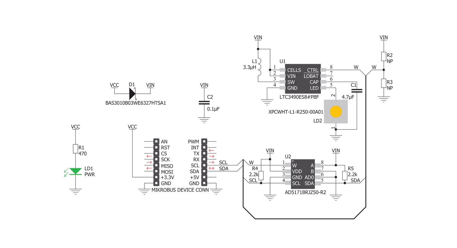
LED Driver 7 Click features the LTC3490, single cell 350mA LED driver from Analog Devices. It provides a constant current drive for 1W LED applications. It is a high-efficiency boost converter. Its key features include the 350mA Constant Current Output, Fixed Frequency Operation: 1.3MHz, Low Quiescent Current: <1mA, and Dimming Control. The LED Driver 7 click also features the AD5171, a 64-position OTP digital potentiometer from Analog Devices. The AD5171 changes the voltage on the CTRL/SHDN pin. This voltage can control the LED drive current from 0mA to 350mA. The AD5171 uses fuse link technology to achieve the memory retention of the resistance setting
function. OTP is a cost-effective alternative over the EEMEM approach for users who do not need to reprogram new memory settings in the digital potentiometer. This device performs the same electronic adjustment function as most mechanical trimmers and variable resistors. The AD5171 is programmed using a 2-wire, I2C compatible digital control. It allows unlimited adjustments before permanently setting the resistance value. During the OTP activation, a permanent fuse blown command is sent after the final value is determined, freezing the wiper position at a given setting (analogous to placing epoxy on a mechanical trimmer). Given the
options its features offer, the LED Driver 7 click is ideally used for Portable lighting, rechargeable flashlights, system calibrations, electronics level settings, automotive electronics adjustments, mechanical trimmers, and potentiometer replacements. This Click board™ can be operated only with a 3.3V logic voltage level. The board must perform appropriate logic voltage level conversion before using MCUs with different logic levels. Also, it comes equipped with a library containing functions and an example code that can be used as a reference for further development.


Features overview
Development board
EasyPIC PRO v8 is a development board specially designed for the needs of rapid development of embedded applications. It supports many high pin count 8-bit PIC microcontrollers from Microchip, regardless of their number of pins, and a broad set of unique functions, such as the first-ever embedded debugger/programmer over WiFi. The development board is well organized and designed so that the end-user has all the necessary elements, such as switches, buttons, indicators, connectors, and others, in one place. Thanks to innovative manufacturing technology, EasyPIC PRO v8 provides a fluid and immersive working experience, allowing access anywhere and under
any circumstances at any time. Each part of the EasyPIC PRO v8 development board contains the components necessary for the most efficient operation of the same board. In addition to the advanced integrated CODEGRIP programmer/debugger module, which offers many valuable programming/debugging options and seamless integration with the Mikroe software environment, the board also includes a clean and regulated power supply module for the development board. It can use a wide range of external power sources, including a battery, an external 12V power supply, and a power source via the USB Type-C (USB-C) connector.
Communication options such as USB-UART, USB DEVICE, and Ethernet are also included, including the well-established mikroBUS™ standard, a standardized socket for the MCU card (SiBRAIN standard), and two display options (graphical and character-based LCD). EasyPIC PRO v8 is an integral part of the Mikroe ecosystem for rapid development. Natively supported by Mikroe software tools, it covers many aspects of prototyping and development thanks to a considerable number of different Click boards™ (over a thousand boards), the number of which is growing every day.

Microcontroller Overview
MCU Card / MCU
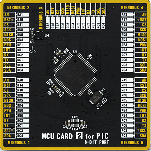
Type
8th Generation
Architecture
PIC
MCU Memory (KB)
64
Silicon Vendor
Microchip
Pin count
80
RAM (Bytes)
3862
Used MCU Pins
mikroBUS™ mapper
Take a closer look
Click board™ Schematic
Step by step
Project assembly

Start by selecting your development board and Click board™. Begin with the EasyPIC PRO v8 as your development board.


Software Support
Library Description
This library contains API for LED Driver 7 Click driver.
Key functions:
leddriver7_generic_write- Generic write functionleddriver7_generic_read- Generic read function.
Open Source
Code example
The complete application code and a ready-to-use project are available through the NECTO Studio Package Manager for direct installation in the NECTO Studio. The application code can also be found on the MIKROE GitHub account.
/*!
 * \file
 * \brief LedDriver7 Click example
 *
 * # Description
 * This application is portable lighting and rechargeable flashlights.
 *
 * The demo application is composed of two sections :
 *
 * ## Application Init
 * Initalizes I2C driver and writes an initial log.
 *
 * ## Application Task
 * This example demonstrates the use of LED Driver 7 Click board,
 * by cycling wiper positions of AD5171 Digital Potentiometer.
 *
 * \author MikroE Team
 *
 */
// ------------------------------------------------------------------- INCLUDES

#include "board.h"
#include "log.h"
#include "leddriver7.h"

// ------------------------------------------------------------------ VARIABLES

static leddriver7_t leddriver7;
static log_t logger;

// ------------------------------------------------------ APPLICATION FUNCTIONS

void application_init ( void )
{
    log_cfg_t log_cfg;
    leddriver7_cfg_t cfg;

    /**
     * Logger initialization.
     * Default baud rate: 115200
     * Default log level: LOG_LEVEL_DEBUG
     * @note If USB_UART_RX and USB_UART_TX
     * are defined as HAL_PIN_NC, you will
     * need to define them manually for log to work.
     * See @b LOG_MAP_USB_UART macro definition for detailed explanation.
     */
    LOG_MAP_USB_UART( log_cfg );
    log_init( &logger, &log_cfg );
    log_info( &logger, "---- Application Init ----" );

    //  Click initialization.

    leddriver7_cfg_setup( &cfg );
    LEDDRIVER7_MAP_MIKROBUS( cfg, MIKROBUS_1 );
    leddriver7_init( &leddriver7, &cfg );

    Delay_ms ( 100 );
    log_printf( &logger, "-------------------- \r\n" );
    log_printf( &logger, " LED Driver 7 Click  \r\n" );
    log_printf( &logger, "-------------------- \r\n" );
}

void application_task ( void )
{
    uint8_t n_pos = 0;
    uint8_t pos_num = 64;

    for ( n_pos = 12; n_pos < pos_num; n_pos++ )
    {
        leddriver7_generic_write( &leddriver7, LEDDRIVER7_NORM_OP_MODE, &n_pos, 1 );
        log_printf( &logger, "Position : %d \r\n", (uint16_t)n_pos );
        Delay_ms ( 500 );
    }
}

int main ( void )
{
    /* Do not remove this line or clock might not be set correctly. */
    #ifdef PREINIT_SUPPORTED
    preinit();
    #endif

    application_init( );

    for ( ; ; )
    {
        application_task( );
    }

    return 0;
}

// ------------------------------------------------------------------------ END
Additional Support
Resources
Category:LED Drivers


