Monitor your heart's activity with MAX30100 and STM32F446RE
Track your heart's every beat

Published Jul 01, 2023
Click board™
Heart rate Click
Dev. board
Fusion for STM32 v8
Compiler
NECTO Studio
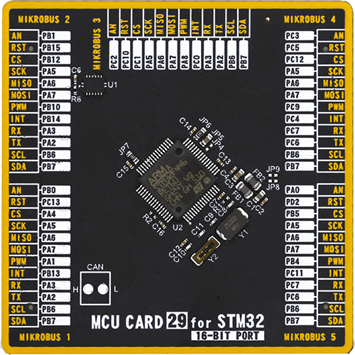
MCU
STM32F446RE
Deliver dependable and precise monitoring that empowers you to make informed decisions regarding your health and well-being
A
A
Hardware Overview
How does it work?
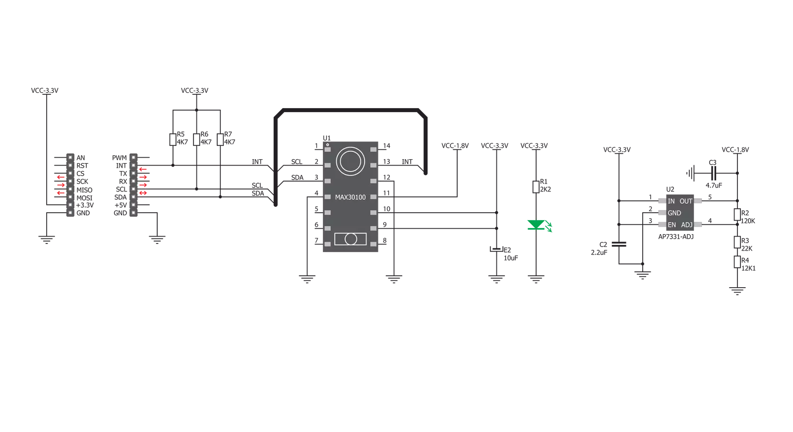
Heart Rate Click is based on the MAX30100, a pulse oximeter, and a heart rate sensor from Analog Devices. This sensor features two integrated LEDs, the RED and IR LEDs. The reflected light is detected by a red/IR photo-detector element and sampled by a low noise delta-sigma 16bit ADC. The analog front end of the MAX30100 sensor features an Ambient Light Cancellation (ALC) section, which eliminates light pollution of the photo-detector element. A discrete-time filter filters
the 16-bit ADC to prevent 50/60Hz interference and hum. The output sampling frequency can be adjusted from 50Hz to 1kHz. There is also a temperature sensor, which can compensate for the environmental changes and calibrate the measurements. Heart Rate Click uses a standard 2-Wire I2C interface to communicate with the host MCU. The interrupt over the INT pin can be generated from five different sources: power ready, SpO2 ready, HR read, temp ready, and FIFO full.
The MAX30100 sensor has the FIFO buffer, which is 16 words deep. This Click board™ can be operated only with a 3.3V logic voltage level. The board must perform appropriate logic voltage level conversion before using MCUs with different logic levels. Also, this Click board™ comes equipped with a library containing easy-to-use functions and an example code that can be used as a reference for further development.

Features overview
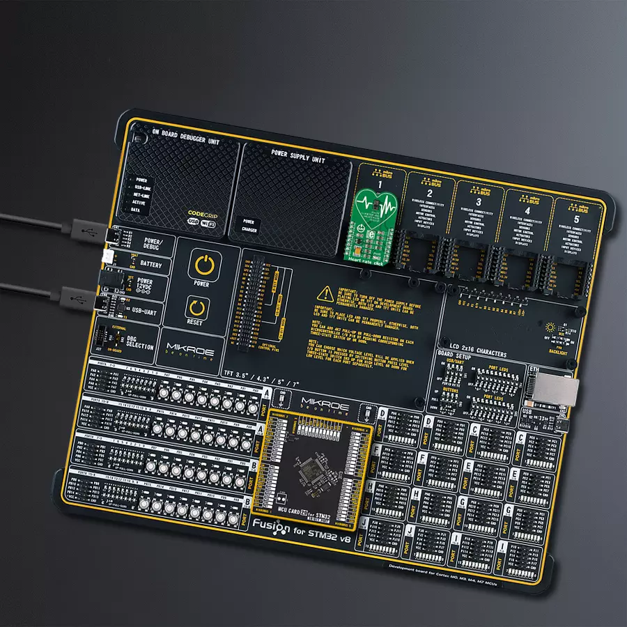
Development board
Fusion for STM32 v8 is a development board specially designed for the needs of rapid development of embedded applications. It supports a wide range of microcontrollers, such as different 32-bit ARM® Cortex®-M based MCUs from STMicroelectronics, regardless of their number of pins, and a broad set of unique functions, such as the first-ever embedded debugger/programmer over WiFi. The development board is well organized and designed so that the end-user has all the necessary elements, such as switches, buttons, indicators, connectors, and others, in one place. Thanks to innovative manufacturing technology, Fusion for STM32 v8 provides a fluid and immersive working experience, allowing
access anywhere and under any circumstances at any time. Each part of the Fusion for STM32 v8 development board contains the components necessary for the most efficient operation of the same board. An advanced integrated CODEGRIP programmer/debugger module offers many valuable programming/debugging options, including support for JTAG, SWD, and SWO Trace (Single Wire Output)), and seamless integration with the Mikroe software environment. Besides, it also includes a clean and regulated power supply module for the development board. It can use a wide range of external power sources, including a battery, an external 12V power supply, and a power source via the USB Type-C (USB-C) connector.
Communication options such as USB-UART, USB HOST/DEVICE, CAN (on the MCU card, if supported), and Ethernet is also included. In addition, it also has the well-established mikroBUS™ standard, a standardized socket for the MCU card (SiBRAIN standard), and two display options for the TFT board line of products and character-based LCD. Fusion for STM32 v8 is an integral part of the Mikroe ecosystem for rapid development. Natively supported by Mikroe software tools, it covers many aspects of prototyping and development thanks to a considerable number of different Click boards™ (over a thousand boards), the number of which is growing every day.

Microcontroller Overview
MCU Card / MCU
Type
8th Generation
Architecture
ARM Cortex-M4
MCU Memory (KB)
512
Silicon Vendor
STMicroelectronics
Pin count
64
RAM (Bytes)
131072
Used MCU Pins
mikroBUS™ mapper
Take a closer look
Click board™ Schematic
Step by step
Project assembly

Start by selecting your development board and Click board™. Begin with the Fusion for STM32 v8 as your development board.


Software Support
Library Description
This library contains API for Heart rate Click driver.
Key functions:
heartrate_data_ready- Using this function we can check if the data is ready for readingheartrate_read_ir_red- Using this function we can read IR and RED valuesheartrate_generic_read- This function reads data from the desired register
Open Source
Code example
The complete application code and a ready-to-use project are available through the NECTO Studio Package Manager for direct installation in the NECTO Studio. The application code can also be found on the MIKROE GitHub account.
/*!
 * \file
 * \brief HeartRate Click example
 *
 * # Description
 * This Click features an advanced oximeter and heart rate monitoring sensor,
 * which relies on two integrated LEDs. It is enough to place an index finger on a top
 * of the sensor to get both of the heart rate and blood oxygen saturation via the I2C interface.
 *
 * The demo application is composed of two sections :
 *
 * ## Application Init
 * Initializes heartrate driver and set the Click board default configuration.
 *
 * ## Application Task
 * Reading values from both Ir and Red diode and displaying their average values on the USB UART.
 *
 * \author MikroE Team
 *
 */
// ------------------------------------------------------------------- INCLUDES

#include "board.h"
#include "log.h"
#include "heartrate.h"

// ------------------------------------------------------------------ VARIABLES

static heartrate_t heartrate;
static log_t logger;

static uint16_t  counter = 500;
static uint8_t  sample_num;

static uint16_t ir_buff[ 16 ]  = { 0 };
static uint16_t red_buff[ 16 ] = { 0 };
static uint32_t ir_average;
static uint32_t red_average;

// ------------------------------------------------------ APPLICATION FUNCTIONS

void application_init ( void )
{
    log_cfg_t log_cfg;
    heartrate_cfg_t cfg;

    /**
     * Logger initialization.
     * Default baud rate: 115200
     * Default log level: LOG_LEVEL_DEBUG
     * @note If USB_UART_RX and USB_UART_TX
     * are defined as HAL_PIN_NC, you will
     * need to define them manually for log to work.
     * See @b LOG_MAP_USB_UART macro definition for detailed explanation.
     */
    LOG_MAP_USB_UART( log_cfg );
    log_init( &logger, &log_cfg );
    log_info( &logger, "---- Application Init ----" );

    //  Click initialization.

    heartrate_cfg_setup( &cfg );
    HEARTRATE_MAP_MIKROBUS( cfg, MIKROBUS_1 );
    heartrate_init( &heartrate, &cfg );

    heartrate_default_cfg( &heartrate );
    Delay_ms ( 100 );
}

void application_task ( void )
{
    if ( heartrate_data_ready( &heartrate ) )
    {
        sample_num = heartrate_read_ir_red( &heartrate, ir_buff, red_buff );
        if ( sample_num > 0 )
        {
            ir_average = 0;
            red_average = 0;
            for ( uint8_t cnt = 0; cnt < sample_num; cnt++ )
            {
                ir_average += ir_buff[ cnt ];
                red_average += red_buff[ cnt ];
            }
            ir_average  /= sample_num;
            red_average /= sample_num;
            counter++;
            if( red_average > 100 && ir_average > 100 )
            {
                log_printf( &logger, "%lu;%lu;\r\n", red_average, ir_average );
                counter = 500;
            }
            else
            {
                if ( counter > 500 )
                {
                    log_printf( &logger, "Please place your index finger on the sensor.\r\n" );
                    counter = 0;
                }
            }
        }
    }
}

int main ( void )
{
    /* Do not remove this line or clock might not be set correctly. */
    #ifdef PREINIT_SUPPORTED
    preinit();
    #endif

    application_init( );

    for ( ; ; )
    {
        application_task( );
    }

    return 0;
}


// ------------------------------------------------------------------------ END
Additional Support
Resources
Category:Biometrics


