Get insights into muscle activity with MCP609 and PIC32MZ1024EFH064
Optimize your workouts with monitoring

Published Jul 27, 2023
Click board™
EMG Click
Dev. board
PIC32MZ clicker
Compiler
NECTO Studio
MCU
PIC32MZ1024EFH064
Enhance your solution's diagnostic capabilities by incorporating cutting-edge techniques for measuring the electrical activity of muscles, providing precise and valuable insights into muscular performance and health
A
A
Hardware Overview
How does it work?
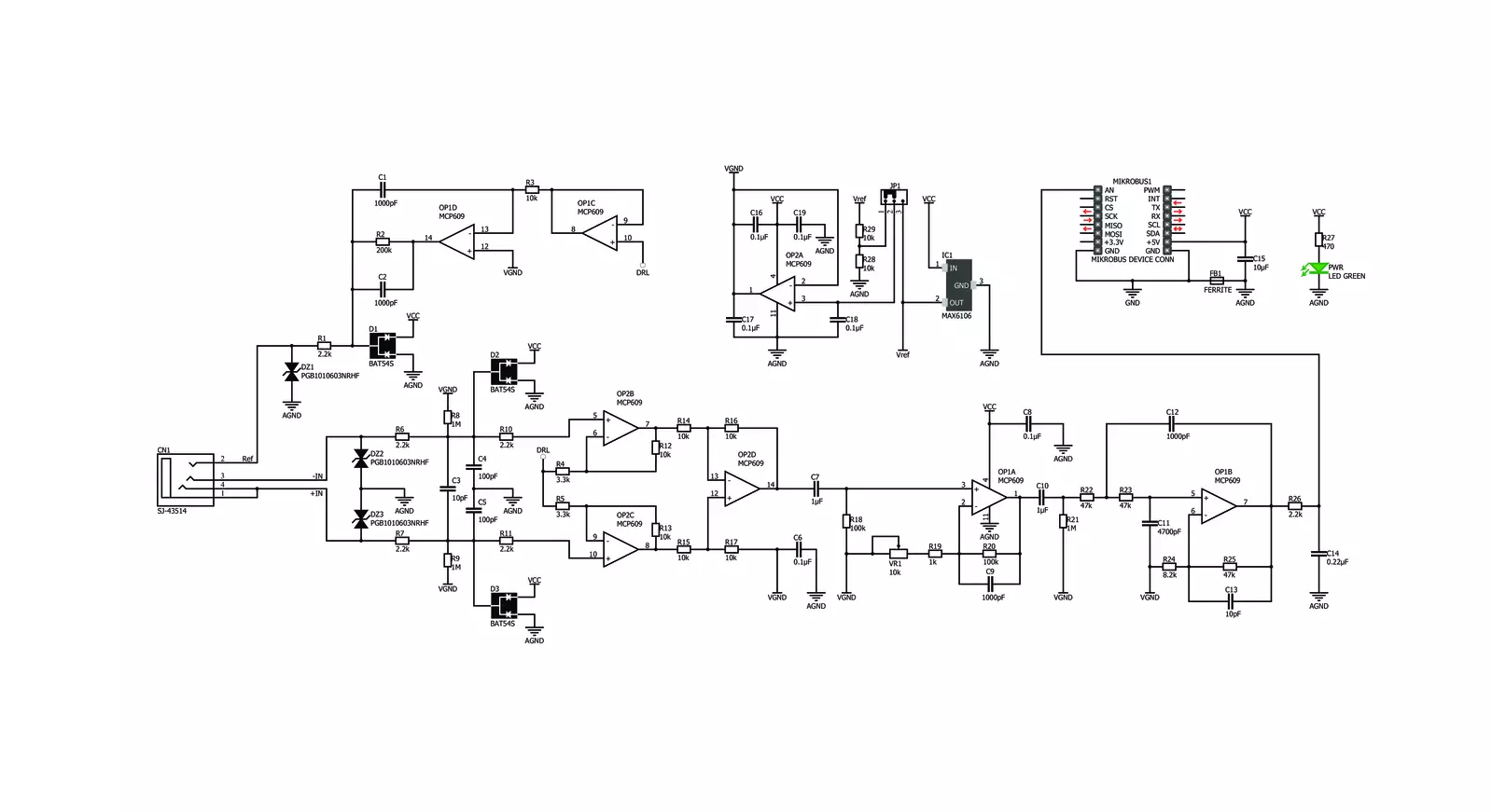
EMG Click is based on the MCP609 operational amplifier from Microchip and MAX6106 micropower voltage reference, serving as a solution that measures the electrical activity produced by the skeletal muscles. EMG click is designed to run on a 5V power supply. The click board™ has an analog output (AN pin).
Electromyography, or EMG, is a diagnostic technique for measuring the electrical activity of muscles. It is often used to diagnose the health of these muscles and the neurons that control them. These neurons are called motor neurons. They transmit electrical signals, and the muscles contract when this happens.
An EMG collects these signals and translates them into a graphical representation. The onboard 3.5mm audio jack is used to connect cables/electrodes to the click board. The electrode collects voltage from the skin (a few millivolts). And the signal from the jack is amplified and filtered. Therefore, EMG Click can be divided into seven blocks.

Features overview
Development board
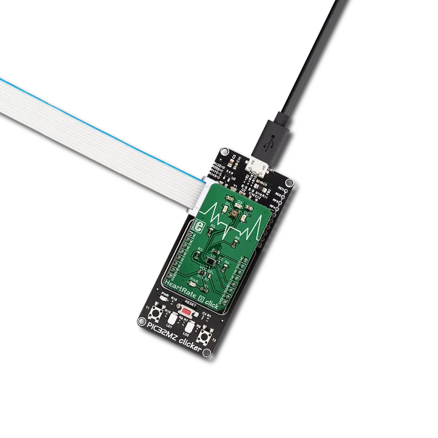
PIC32MZ Clicker is a compact starter development board that brings the flexibility of add-on Click boards™ to your favorite microcontroller, making it a perfect starter kit for implementing your ideas. It comes with an onboard 32-bit PIC32MZ microcontroller with FPU from Microchip, a USB connector, LED indicators, buttons, a mikroProg connector, and a header for interfacing with external electronics. Thanks to its compact design with clear and easy-recognizable silkscreen markings, it provides a fluid and immersive working experience, allowing access anywhere and under
any circumstances. Each part of the PIC32MZ Clicker development kit contains the components necessary for the most efficient operation of the same board. In addition to the possibility of choosing the PIC32MZ Clicker programming method, using USB HID mikroBootloader, or through an external mikroProg connector for PIC, dsPIC, or PIC32 programmer, the Clicker board also includes a clean and regulated power supply module for the development kit. The USB Micro-B connection can provide up to 500mA of current, which is more than enough to operate all onboard
and additional modules. All communication methods that mikroBUS™ itself supports are on this board, including the well-established mikroBUS™ socket, reset button, and several buttons and LED indicators. PIC32MZ Clicker is an integral part of the Mikroe ecosystem, allowing you to create a new application in minutes. Natively supported by Mikroe software tools, it covers many aspects of prototyping thanks to a considerable number of different Click boards™ (over a thousand boards), the number of which is growing every day.

Microcontroller Overview
MCU Card / MCU

Architecture
PIC32
MCU Memory (KB)
1024
Silicon Vendor
Microchip
Pin count
64
RAM (Bytes)
524288
You complete me!
Accessories
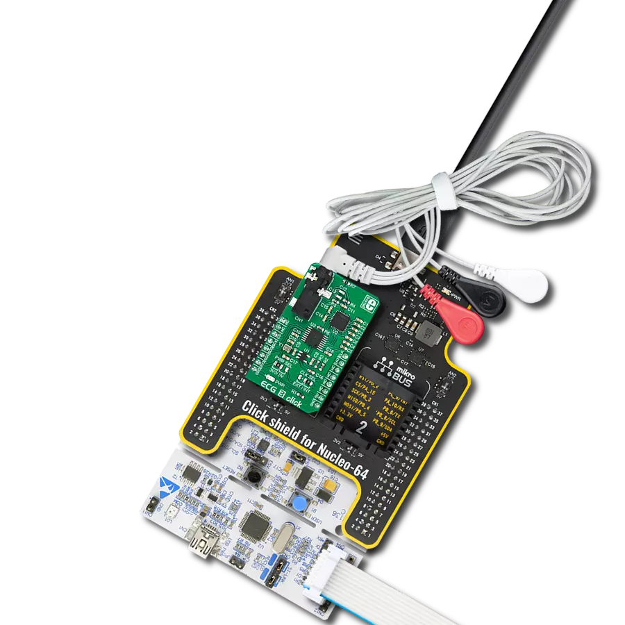
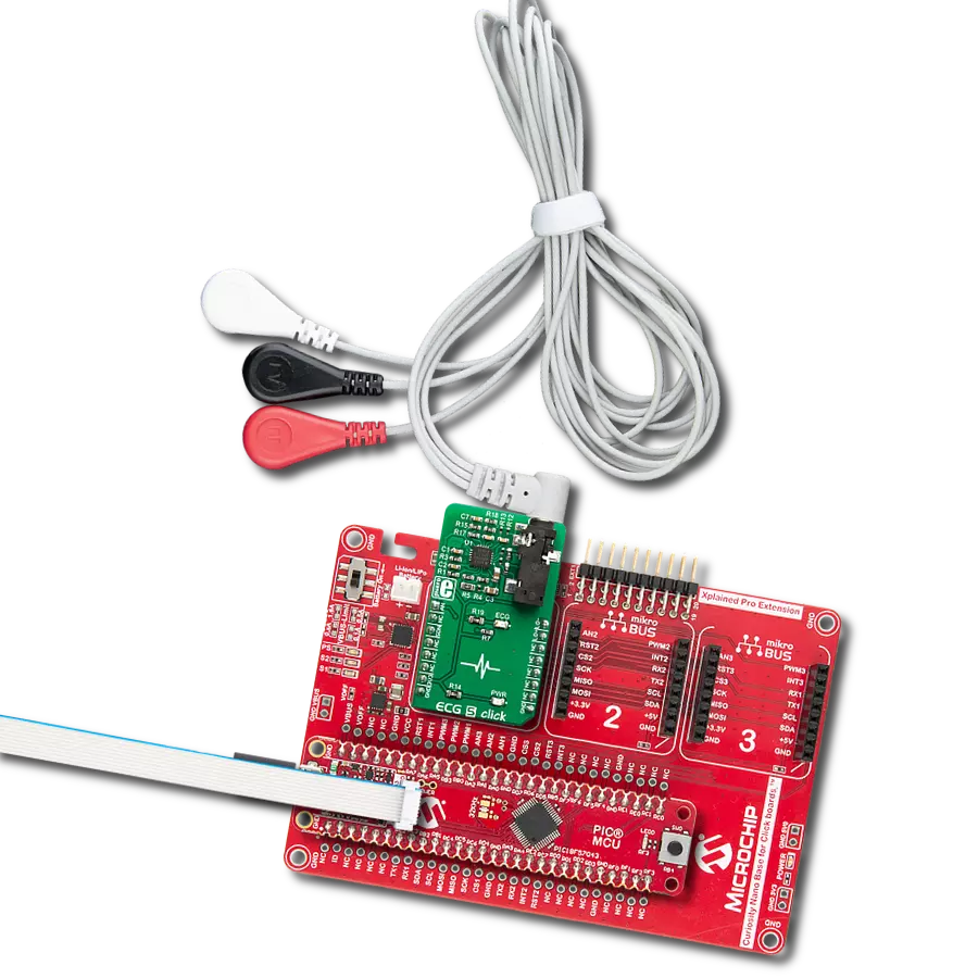
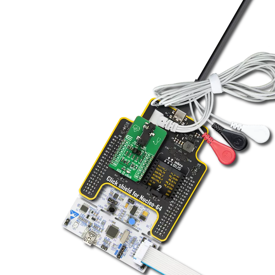
3-wire ECG/EMG cable comes with a convenient 3.5mm phone jack, and it is designed for electrocardiogram recording. This 1m cable is a practical companion for medical professionals and enthusiasts. To complement this cable, you can also use single-use adhesive ECG/EMG electrodes measuring 48x34mm, each equipped with an ECG/EMG cable stud adapter. These electrodes ensure a seamless experience when paired with our ECG/EMG cable and guarantee reliable ECG/EMG signal transmission for comprehensive cardiac monitoring. Trust in the accuracy and convenience of this setup to effortlessly record electrocardiograms and electromyograms with confidence.

Used MCU Pins
mikroBUS™ mapper
Take a closer look
Click board™ Schematic
Step by step
Project assembly

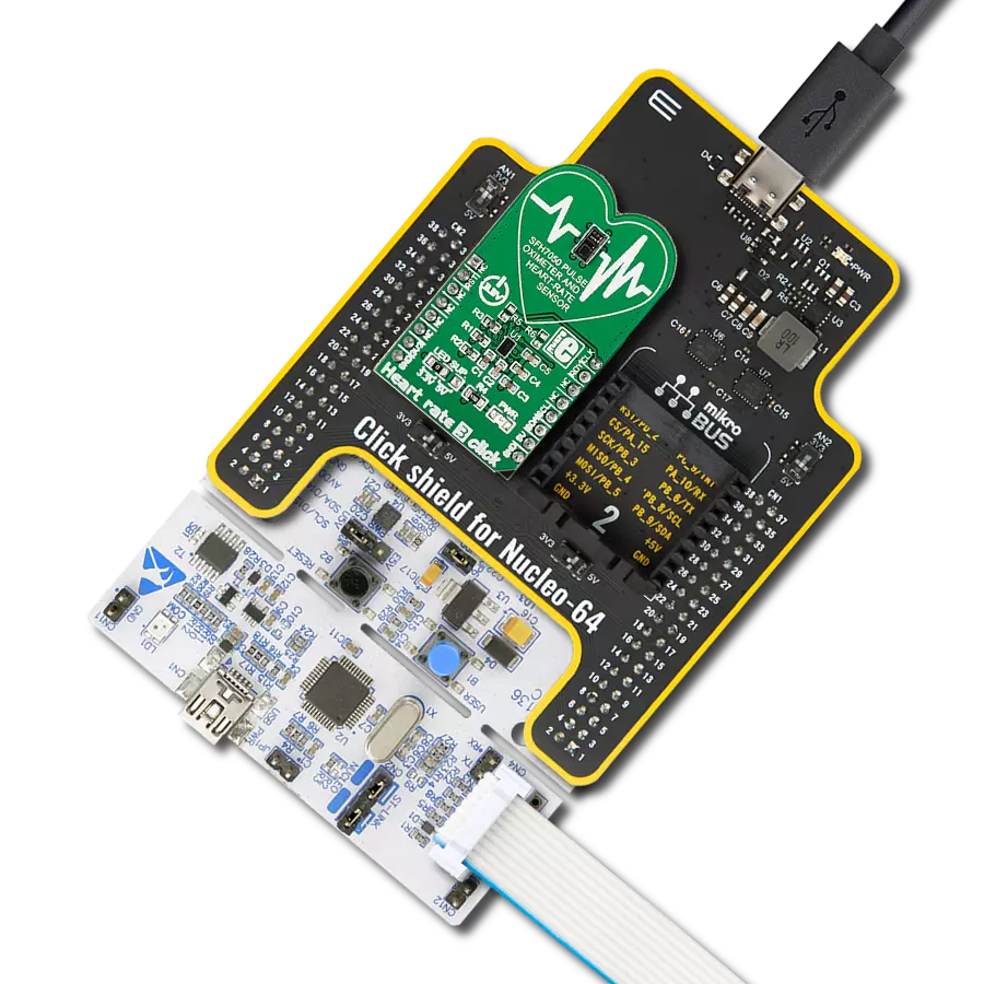
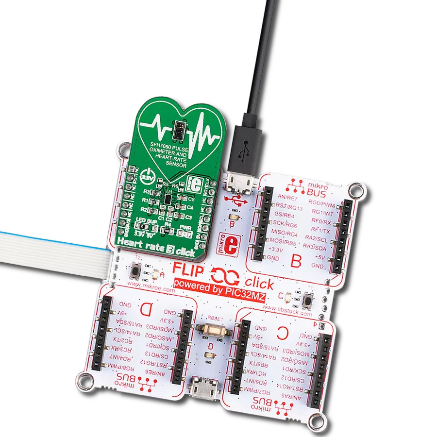
Start by selecting your development board and Click board™. Begin with the PIC32MZ clicker as your development board.


Track your results in real time
Application Output
1. Application Output - In Debug mode, the 'Application Output' window enables real-time data monitoring, offering direct insight into execution results. Ensure proper data display by configuring the environment correctly using the provided tutorial.

2. UART Terminal - Use the UART Terminal to monitor data transmission via a USB to UART converter, allowing direct communication between the Click board™ and your development system. Configure the baud rate and other serial settings according to your project's requirements to ensure proper functionality. For step-by-step setup instructions, refer to the provided tutorial.

3. Plot Output - The Plot feature offers a powerful way to visualize real-time sensor data, enabling trend analysis, debugging, and comparison of multiple data points. To set it up correctly, follow the provided tutorial, which includes a step-by-step example of using the Plot feature to display Click board™ readings. To use the Plot feature in your code, use the function: plot(*insert_graph_name*, variable_name);. This is a general format, and it is up to the user to replace 'insert_graph_name' with the actual graph name and 'variable_name' with the parameter to be displayed.

Software Support
Library Description
This library contains API for EMG Click driver.
Key functions:
emg_read_an_pin_value- EMG read AN pin value functionemg_read_an_pin_voltage- EMG read AN pin voltage level function
Open Source
Code example
The complete application code and a ready-to-use project are available through the NECTO Studio Package Manager for direct installation in the NECTO Studio. The application code can also be found on the MIKROE GitHub account.
/*!
 * @file main.c
 * @brief EMG Click Example.
 *
 * # Description
 * This is an example which demonstrates the use of EMG Click board.
 *
 * The demo application is composed of two sections :
 *
 * ## Application Init
 * Initializes ADC and timer counter.
 *
 * ## Application Task
 * Reads ADC value and sends results on serial plotter every 5 ms.
 *
 * @author Stefan Ilic
 *
 */

#include "board.h"
#include "log.h"
#include "emg.h"

static emg_t emg;   /**< EMG Click driver object. */
static log_t logger;    /**< Logger object. */
uint32_t time;

void application_init ( void ) {
    log_cfg_t log_cfg;  /**< Logger config object. */
    emg_cfg_t emg_cfg;  /**< Click config object. */

    /**
     * Logger initialization.
     * Default baud rate: 115200
     * Default log level: LOG_LEVEL_DEBUG
     * @note If USB_UART_RX and USB_UART_TX
     * are defined as HAL_PIN_NC, you will
     * need to define them manually for log to work.
     * See @b LOG_MAP_USB_UART macro definition for detailed explanation.
     */
    LOG_MAP_USB_UART( log_cfg );
    log_init( &logger, &log_cfg );
    log_info( &logger, " Application Init " );

    // Click initialization.
    emg_cfg_setup( &emg_cfg );
    EMG_MAP_MIKROBUS( emg_cfg, MIKROBUS_1 );
    if ( ADC_ERROR == emg_init( &emg, &emg_cfg ) ) {
        log_error( &logger, " Application Init Error. " );
        log_info( &logger, " Please, run program again... " );

        for ( ; ; );
    }
    time = 0;
    log_info( &logger, " Application Task " );
}

void application_task ( void )  {
    uint16_t emg_an = 0;
    if ( emg_read_an_pin_value( &emg, &emg_an ) == ADC_SUCCESS ){
        log_printf( &logger, " %u,%lu\r\n ", emg_an, time );
    }
    time += 5;
    Delay_ms ( 5 );
}

int main ( void )
{
    /* Do not remove this line or clock might not be set correctly. */
    #ifdef PREINIT_SUPPORTED
    preinit();
    #endif

    application_init( );

    for ( ; ; )
    {
        application_task( );
    }

    return 0;
}

// ------------------------------------------------------------------------ END