Bridge the gap between RS232 and SPI interfaces using MAX3100 and STM32F215RE
From RS232 to SPI: A revolution in data transformation

Published Oct 19, 2023
Click board™
RS232 SPI Click
Dev. board
Fusion for STM32 v8
Compiler
NECTO Studio
MCU
STM32F215RE
Effortlessly convert RS232 data into the SPI format with our user-friendly solution, streamlining the process of modernizing data communication
A
A
Hardware Overview
How does it work?
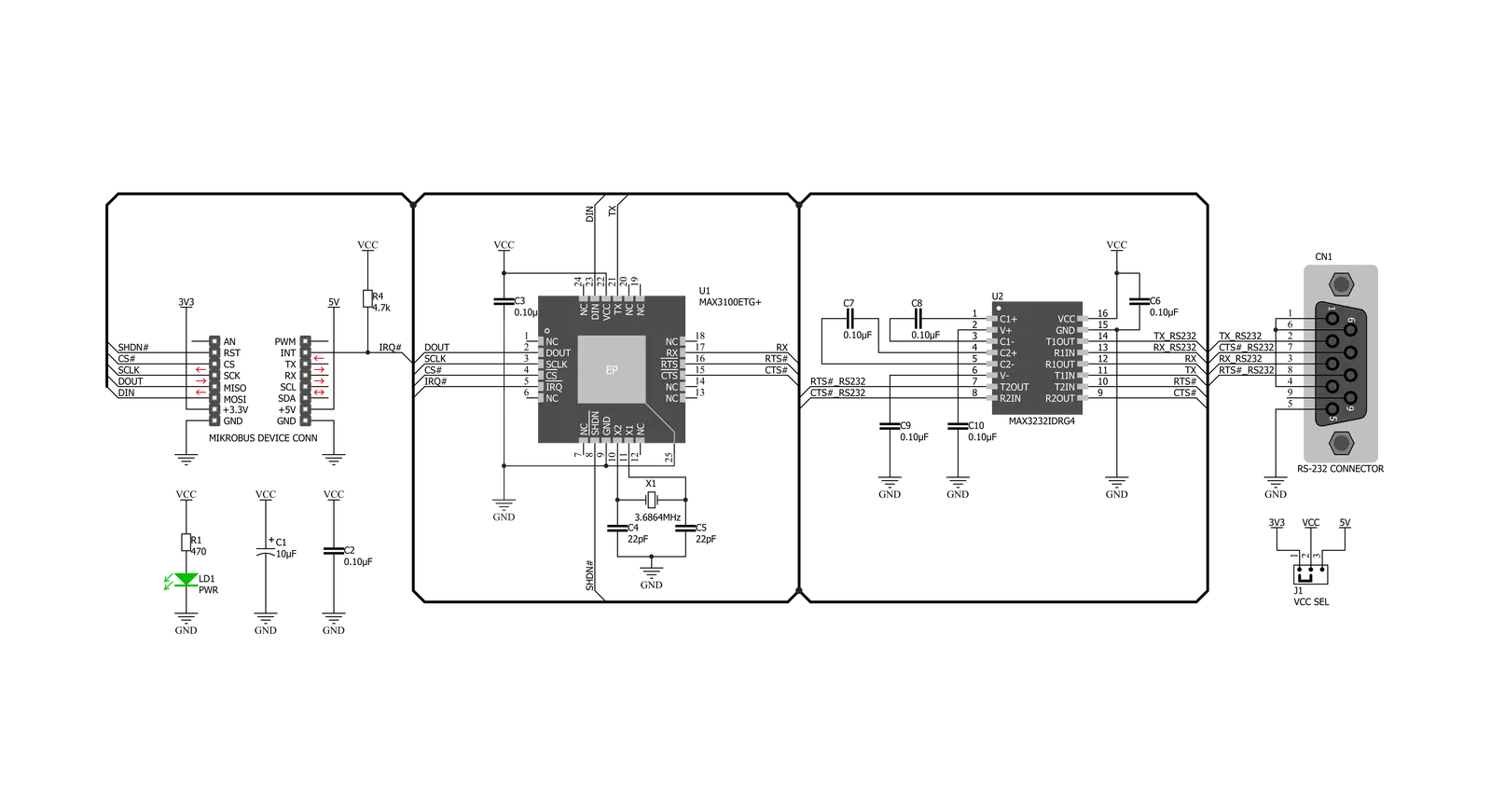
RS232 SPI Click is based on two ICs - MAX3100 and MAX3232. The MAX3100 serves as UART interface to the SPI/MICROWIRE compatible interface converter. In the same time, MAX3232 device enables RS232 SPI click to meet the requirements of TIA/EIA-232-F and also provides the electrical interface between an asynchronous communication controller and the serial-port connector. The charge pump and four small external capacitors allow operation from a single 3-V to 5.5-V supply. RS232 SPI click Uses an SPI™/MICROWIRE™ interface for communication with the host microcontroller (µC). Then, the MAX3100 is responsible for conversion from synchronous serial data from a microcontroller to asynchronous, serial-data communication port such as RS-232, RS-485, IrDA. In this case the
RS232 protocol is used. The MAX3100 includes a crystal oscillator and a baud rate generator with software-programmable divider ratios for all common baud rates from 300 baud to 230k baud. The transmitter section accepts SPI/MICROWIRE data, formats it, and transmits it in asynchronous serial format from the TX output. Data is loaded into the transmit buffer register from the SPI/MICROWIRE interface. The MAX3100 adds start and stop bits to the data and clocks the data out at the selected baud rate. A software- or hardware-invoked shutdown lowers quiescent current to 10µA, while allowing the MAX3100 to detect receiver activity. An 8-word-deep first-in/first-out (FIFO) buffer minimizes processor overhead. This device also includes a flexible interrupt with four maskable sources, including address recognition
on 9-bit networks. Two hardware-handshaking control lines are included (one input and one output). Because of the features contained in its modules, the RS232 SPI click can be used for handheld instruments, UART in SPI systems, small networks in HVAC or Building control, battery-powered systems, PDAs, notebooks and many more. This Click board™ can operate with either 3.3V or 5V logic voltage levels selected via the VCC SEL jumper. This way, both 3.3V and 5V capable MCUs can use the communication lines properly. Also, this Click board™ comes equipped with a library containing easy-to-use functions and an example code that can be used as a reference for further development.


Features overview
Development board
Fusion for STM32 v8 is a development board specially designed for the needs of rapid development of embedded applications. It supports a wide range of microcontrollers, such as different 32-bit ARM® Cortex®-M based MCUs from STMicroelectronics, regardless of their number of pins, and a broad set of unique functions, such as the first-ever embedded debugger/programmer over WiFi. The development board is well organized and designed so that the end-user has all the necessary elements, such as switches, buttons, indicators, connectors, and others, in one place. Thanks to innovative manufacturing technology, Fusion for STM32 v8 provides a fluid and immersive working experience, allowing
access anywhere and under any circumstances at any time. Each part of the Fusion for STM32 v8 development board contains the components necessary for the most efficient operation of the same board. An advanced integrated CODEGRIP programmer/debugger module offers many valuable programming/debugging options, including support for JTAG, SWD, and SWO Trace (Single Wire Output)), and seamless integration with the Mikroe software environment. Besides, it also includes a clean and regulated power supply module for the development board. It can use a wide range of external power sources, including a battery, an external 12V power supply, and a power source via the USB Type-C (USB-C) connector.
Communication options such as USB-UART, USB HOST/DEVICE, CAN (on the MCU card, if supported), and Ethernet is also included. In addition, it also has the well-established mikroBUS™ standard, a standardized socket for the MCU card (SiBRAIN standard), and two display options for the TFT board line of products and character-based LCD. Fusion for STM32 v8 is an integral part of the Mikroe ecosystem for rapid development. Natively supported by Mikroe software tools, it covers many aspects of prototyping and development thanks to a considerable number of different Click boards™ (over a thousand boards), the number of which is growing every day.

Microcontroller Overview
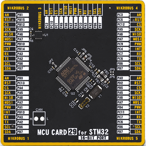
MCU Card / MCU
Type
8th Generation
Architecture
ARM Cortex-M3
MCU Memory (KB)
512
Silicon Vendor
STMicroelectronics
Pin count
64
RAM (Bytes)
131072
You complete me!
Accessories
DB9 Cable Female-to-Female (2m) cable is essential for establishing dependable serial data connections between devices. With its DB9 female connectors on both ends, this cable enables a seamless link between various equipment, such as computers, routers, switches, and other serial devices. Measuring 2 meters in length, it offers flexibility in arranging your setup without compromising data transmission quality. Crafted with precision, this cable ensures consistent and reliable data exchange, making it suitable for industrial applications, office environments, and home setups. Whether configuring networking equipment, accessing console ports, or utilizing serial peripherals, this cable's durable construction and robust connectors guarantee a stable connection. Simplify your data communication needs with the 2m DB9 female-to-female cable, an efficient solution designed to meet your serial connectivity requirements easily and efficiently.

Used MCU Pins
mikroBUS™ mapper
Take a closer look
Click board™ Schematic
Step by step
Project assembly

Start by selecting your development board and Click board™. Begin with the Fusion for STM32 v8 as your development board.


Software Support
Library Description
This library contains API for RS232 SPI Click driver.
Key functions:
rs232spi_reg_write- This function writes two bytes of data using the SPI serial interface.rs232spi_reg_read- This function reads two bytes of data using the SPI serial interface.rs232spi_digital_write_rst- This function writes the specified digital signal to the RST pin.
Open Source
Code example
The complete application code and a ready-to-use project are available through the NECTO Studio Package Manager for direct installation in the NECTO Studio. The application code can also be found on the MIKROE GitHub account.
/*!
 * \file
 * \brief Rs232Spi Click example
 *
 * # Description
 * This example showcases how to initialize and use the RS232 SPI Click. The Click has a uni-
 * versal asynchronous transceiver which uses a SPI serial interface to communicate with the
 * MCU. In order for this example to work, 2 Clicks are needed - a receiver and a transmitter.
 *
 * The demo application is composed of two sections :
 *
 * ## Application Init
 * This function initializes and configures the logger and Click modules. Additional configura-
 * ting is done in the default_cfg(...) function.
 *
 * ## Application Task
 * This function receives and displays UART data in the "read mode" and sends the predefined
 * message in the "write mode".
 *
 * \author MikroE Team
 *
 */
// ------------------------------------------------------------------- INCLUDES

#include "board.h"
#include "log.h"
#include "rs232spi.h"

// ------------------------------------------------------------------ VARIABLES

static rs232spi_t rs232spi;
static log_t logger;

static const uint8_t message[ 9 ] = { 'M', 'i', 'k', 'r', 'o', 'E', 13, 10, 0 };

static const uint8_t RX_MODE = 1;
static const uint8_t TX_MODE = 0;

// ------------------------------------------------------ APPLICATION FUNCTIONS

void application_init ( )
{
    log_cfg_t log_cfg;
    rs232spi_cfg_t cfg;

    /**
     * Logger initialization.
     * Default baud rate: 115200
     * Default log level: LOG_LEVEL_DEBUG
     * @note If USB_UART_RX and USB_UART_TX
     * are defined as HAL_PIN_NC, you will
     * need to define them manually for log to work.
     * See @b LOG_MAP_USB_UART macro definition for detailed explanation.
     */
    LOG_MAP_USB_UART( log_cfg );
    log_init( &logger, &log_cfg );
    log_info( &logger, "---- Application Init ----" );

    //  Click initialization.

    rs232spi_cfg_setup( &cfg );
    RS232SPI_MAP_MIKROBUS( cfg, MIKROBUS_1 );
    rs232spi_init( &rs232spi, &cfg );
    Delay_ms ( 100 );
    rs232spi_digital_write_rst( &rs232spi, 1 );
    Delay_ms ( 100 );
    rs232spi_default_cfg( &rs232spi, 115200 );
    Delay_ms ( 100 );
    rs232spi_flush( &rs232spi );
    Delay_ms ( 100 );
    log_printf( &logger, "App init done...\r\n" );
}

void application_task ( )
{
    uint8_t mode = RX_MODE;
    uint8_t cnt;
    char txt;

    if ( mode == RX_MODE )
    {
        if ( rs232spi_data_ready( &rs232spi ) != 0 )
        {
            txt = rs232spi_transfer( &rs232spi, RS232SPI_CMD_READ_DATA );
            log_printf( &logger, "%c", txt );
        }
    }
    else if ( mode == TX_MODE )
    {
        for ( cnt = 0; cnt < 9; cnt++ )
        {
            rs232spi_data_write( &rs232spi, message[ cnt ] );
            Delay_ms ( 500 );
        }
    }
}

int main ( void )
{
    /* Do not remove this line or clock might not be set correctly. */
    #ifdef PREINIT_SUPPORTED
    preinit();
    #endif

    application_init( );

    for ( ; ; )
    {
        application_task( );
    }

    return 0;
}

// ------------------------------------------------------------------------ END
Additional Support
Resources
Category:RS232


