Translate 24V sensor outputs to 5V CMOS-compatible signals with MAX31910 and TM4C129ENCPDT
Your gateway to industrial signal serialization

Published Sep 30, 2023
Click board™
Serializer Click
Dev. board
Fusion for Tiva v8
Compiler
NECTO Studio
MCU
TM4C129ENCPDT
The purpose of this solution is to simplify the complexity of sensor data conversion, empowering your automation projects with efficient 5V CMOS-compatible signals
A
A
Hardware Overview
How does it work?
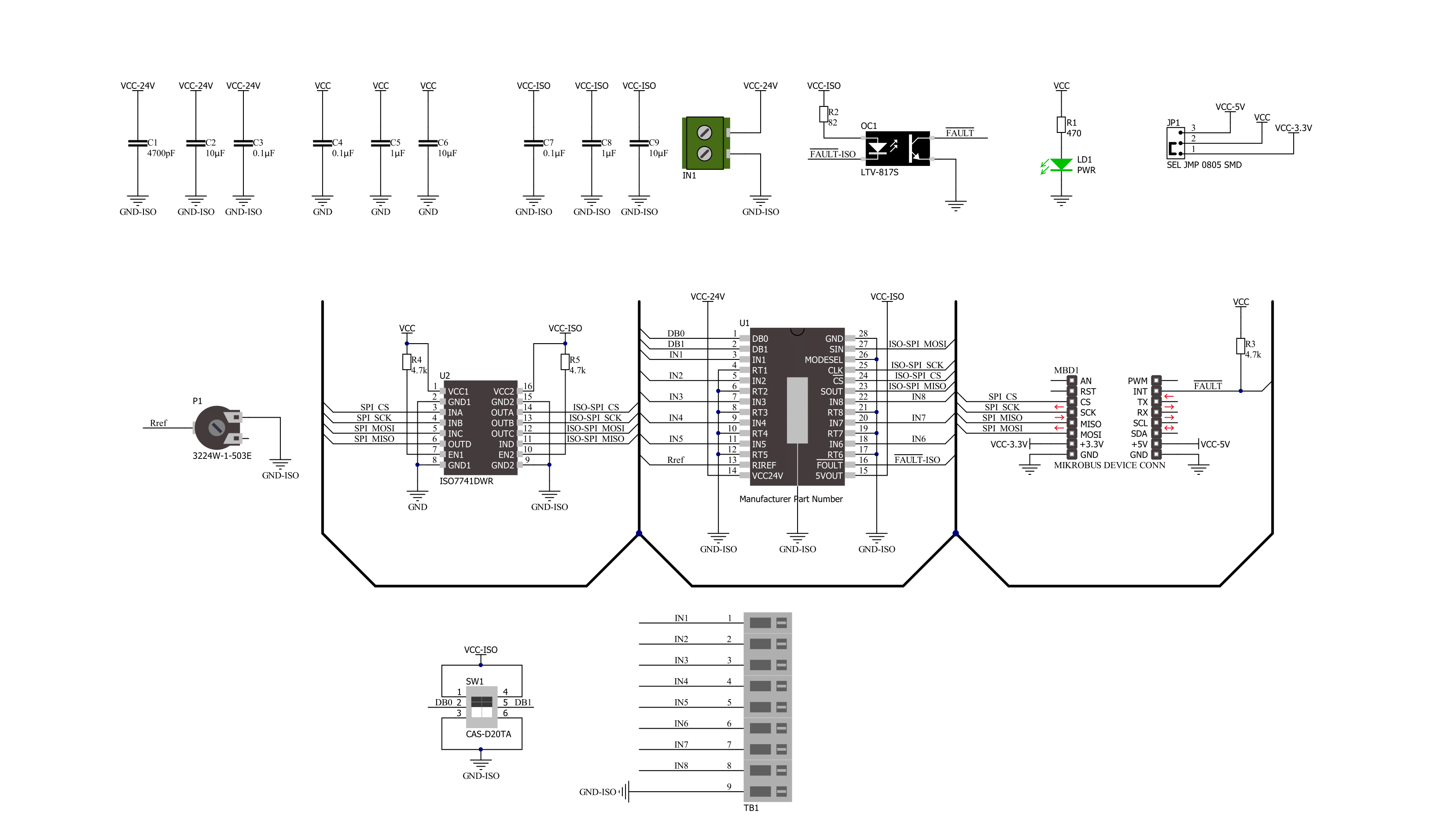
Serializer Click is based on the MAX31910, an eight-channel digital input translator/serializer for high-channel density digital input modules in industrial and process automation from Maxim Integrated, now part of Analog Devices. It features integrated current limiting, low-pass filtering, and channel serialization. Input current limiting allows a significant power reduction consumed from the field voltage supply (external typical 24V) compared to traditional discrete resistor-divider implementations. The device uses patent-pending circuit techniques to reduce power beyond possible input current, further limiting alone. The MAX31910 translates, conditions, and serializes the 24V digital output of sensors and switches to 5V CMOS-compatible signals required by the MCU. It provides the front-end interface circuit of a
programmable logic controller (PLC) digital input module. Selectable on-chip low-pass filters allow flexible debouncing and filtering sensor outputs based on the application. The serializer is stackable so that any number of input channels (IN1-IN8) can be serialized and output through only one SPI-compatible port. The serializer inputs (IN1-IN8) sense field sensors' state (ON vs. OFF) by monitoring both voltage and current flowing through the sensor output. The current sinking through these input pins rises linearly with input voltage until the limit set by the current clamp is reached (set by an onboard potentiometer). Any voltage increase beyond this point does not further increase the input current. Serializer Click communicates with MCU through a standard SPI interface in a configuration with installed digital
isolators (ISO7741 and LTV-817S). Also, it uses an interrupt pin, the FLT pin of the mikroBUS™ socket, as a 'fault' indicator, which immediately notifies the host when a fault such as an overtemperature or undervoltage condition occurs. It also has a two-channel switch labeled DB, determining the current switching frequency. The current switching clock period is automatically selected according to a switch position. This Click board™ can operate with either 3.3V or 5V logic voltage levels selected via the VCC SEL jumper. This way, both 3.3V and 5V capable MCUs can use the communication lines properly. Also, this Click board™ comes equipped with a library containing easy-to-use functions and an example code that can be used as a reference for further development.

Features overview
Development board
Fusion for TIVA v8 is a development board specially designed for the needs of rapid development of embedded applications. It supports a wide range of microcontrollers, such as different 32-bit ARM® Cortex®-M based MCUs from Texas Instruments, regardless of their number of pins, and a broad set of unique functions, such as the first-ever embedded debugger/programmer over a WiFi network. The development board is well organized and designed so that the end-user has all the necessary elements, such as switches, buttons, indicators, connectors, and others, in one place. Thanks to innovative manufacturing technology, Fusion for TIVA v8 provides a fluid and immersive working experience, allowing access
anywhere and under any circumstances at any time. Each part of the Fusion for TIVA v8 development board contains the components necessary for the most efficient operation of the same board. An advanced integrated CODEGRIP programmer/debugger module offers many valuable programming/debugging options, including support for JTAG, SWD, and SWO Trace (Single Wire Output)), and seamless integration with the Mikroe software environment. Besides, it also includes a clean and regulated power supply module for the development board. It can use a wide range of external power sources, including a battery, an external 12V power supply, and a power source via the USB Type-C (USB-C) connector.
Communication options such as USB-UART, USB HOST/DEVICE, CAN (on the MCU card, if supported), and Ethernet is also included. In addition, it also has the well-established mikroBUS™ standard, a standardized socket for the MCU card (SiBRAIN standard), and two display options for the TFT board line of products and character-based LCD. Fusion for TIVA v8 is an integral part of the Mikroe ecosystem for rapid development. Natively supported by Mikroe software tools, it covers many aspects of prototyping and development thanks to a considerable number of different Click boards™ (over a thousand boards), the number of which is growing every day.

Microcontroller Overview
MCU Card / MCU

Type
8th Generation
Architecture
ARM Cortex-M4
MCU Memory (KB)
1024
Silicon Vendor
Texas Instruments
Pin count
128
RAM (Bytes)
262144
Used MCU Pins
mikroBUS™ mapper
Take a closer look
Click board™ Schematic
Step by step
Project assembly

Start by selecting your development board and Click board™. Begin with the Fusion for Tiva v8 as your development board.


Track your results in real time
Application Output
1. Application Output - In Debug mode, the 'Application Output' window enables real-time data monitoring, offering direct insight into execution results. Ensure proper data display by configuring the environment correctly using the provided tutorial.

2. UART Terminal - Use the UART Terminal to monitor data transmission via a USB to UART converter, allowing direct communication between the Click board™ and your development system. Configure the baud rate and other serial settings according to your project's requirements to ensure proper functionality. For step-by-step setup instructions, refer to the provided tutorial.

3. Plot Output - The Plot feature offers a powerful way to visualize real-time sensor data, enabling trend analysis, debugging, and comparison of multiple data points. To set it up correctly, follow the provided tutorial, which includes a step-by-step example of using the Plot feature to display Click board™ readings. To use the Plot feature in your code, use the function: plot(*insert_graph_name*, variable_name);. This is a general format, and it is up to the user to replace 'insert_graph_name' with the actual graph name and 'variable_name' with the parameter to be displayed.

Software Support
Library Description
This library contains API for Serializer Click driver.
Key functions:
serializer_get_flt_pin- This function returns the fault pin logic stateserializer_read_input- This function reads the input data by using SPI serial interface, and then checks the data integrity by verifying the CRC byte.
Open Source
Code example
The complete application code and a ready-to-use project are available through the NECTO Studio Package Manager for direct installation in the NECTO Studio. The application code can also be found on the MIKROE GitHub account.
/*!
 * @file main.c
 * @brief Serializer Click example
 *
 * # Description
 * This example demonstrates the use of a Serializer Click board by reading
 * the state of all inputs and displaying the results on the USB UART.
 *
 * The demo application is composed of two sections :
 *
 * ## Application Init
 * Initializes the driver and logger.
 *
 * ## Application Task
 * Reads the state of all inputs and displays the results on the USB UART
 * approximately once per second. Also, if there's any fault indication detected,
 * it will be displayed accordingly.
 *
 * @author Stefan Filipovic
 *
 */

#include "board.h"
#include "log.h"
#include "serializer.h"

static serializer_t serializer;
static log_t logger;

void application_init ( void )
{
    log_cfg_t log_cfg;  /**< Logger config object. */
    serializer_cfg_t serializer_cfg;  /**< Click config object. */

    /**
     * Logger initialization.
     * Default baud rate: 115200
     * Default log level: LOG_LEVEL_DEBUG
     * @note If USB_UART_RX and USB_UART_TX
     * are defined as HAL_PIN_NC, you will
     * need to define them manually for log to work.
     * See @b LOG_MAP_USB_UART macro definition for detailed explanation.
     */
    LOG_MAP_USB_UART( log_cfg );
    log_init( &logger, &log_cfg );
    log_info( &logger, " Application Init " );

    // Click initialization.
    serializer_cfg_setup( &serializer_cfg );
    SERIALIZER_MAP_MIKROBUS( serializer_cfg, MIKROBUS_1 );
    if ( SPI_MASTER_ERROR == serializer_init( &serializer, &serializer_cfg ) )
    {
        log_error( &logger, " Communication init." );
        for ( ; ; );
    }

    log_info( &logger, " Application Task " );
}

void application_task ( void )
{
    uint8_t input_data = 0;
    err_t status = serializer_read_input ( &serializer, &input_data );

    if ( SERIALIZER_ERROR != status )
    {
        for ( uint8_t cnt = 0; cnt < 8; cnt++ )
        {
            log_printf( &logger, " IN%u: %s\r\n", ( uint16_t ) cnt + 1,
                                                  ( char * ) ( ( input_data & ( 1 << cnt ) ) ? "High" : "Low" ) );
        }
        if ( status & SERIALIZER_STATUS_UNDERVOLTAGE )
        {
            log_info( &logger, "Undervoltage fault" );
        }
        if ( status & SERIALIZER_STATUS_OVERTEMPERATURE )
        {
            log_info( &logger, "Overtemperature fault" );
        }
        log_printf( &logger, "\r\n" );
        Delay_ms ( 1000 );
    }
}

int main ( void )
{
    /* Do not remove this line or clock might not be set correctly. */
    #ifdef PREINIT_SUPPORTED
    preinit();
    #endif

    application_init( );

    for ( ; ; )
    {
        application_task( );
    }

    return 0;
}

// ------------------------------------------------------------------------ END


