Transform the RMS of input signals into a stable DC voltage with LTC1968 and PIC32MZ1024EFH064
From RMS to steady voltage

Published Sep 30, 2023
Click board™
RMS to DC Click
Dev. board
PIC32MZ clicker
Compiler
NECTO Studio
MCU
PIC32MZ1024EFH064
Experience a breakthrough in signal processing with our innovative RMS-to-DC voltage converter, delivering real-time insights through accurate voltage conversion, essential for advanced data analysis
A
A
Hardware Overview
How does it work?
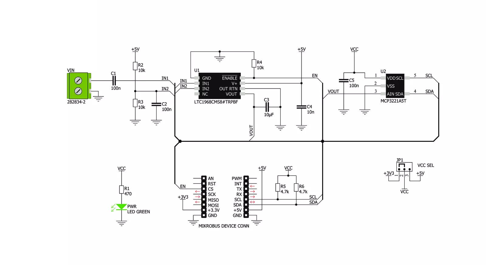
RMS to DC Click is based on the LTC1968, a precise RMS-to-DC converter with the wide input signal bandwidth from the Analog Devices. This IC uses the proprietary delta-sigma computational techniques to achieve a highly linear DC voltage output at its output in respect with the RMS of the input signal. The RMS is typically associated with the alternating signals. This Click board™ is capable of measuring the RMS of both bipolar and unipolar periodically alternating signals, over a wide range of frequencies. The RMS or Root Mean Square is used to describe the power of the input signal: the RMS value of current is equal to a DC current value that would produce the same heat dissipation on the resistive load. Therefore, it is often important to know the RMS value of the signal. RMS to DC click allows measuring of the RMS value of a periodically repetitive signal. As mentioned before, the LTC1968 provides a highly accurate and linear conversion of the RMS value at its input, to a constant voltage at its output. The constant voltage directly depends on the RMS value of the input signal, thanks to the innovative
sigma-delta conversion technique of the LTC1968, which is described in details within the LTC1968 datasheet. Due to a high output voltage linearity, no compensation elements are required, except a single filtering capacitor. The output voltage of the LTC1968 is then fed to an analog-to-digital converter (ADC). For the voltage-to-digital conversion purposes, RMS to DC click utilizes the MCP3221, a 12-bit ADC with I2C interface, from Microchip. This ADC uses the voltage at its power supply pin as a conversion reference. This simplifies the Click board™ schematics, allowing the reference voltage to be changed along with the power supply voltage of the ADC. The communication logic voltage level, as well as the ADC power supply voltage, can be changed by switching the SMD jumper labeled as VCC SEL to either 3V3 position or 5V position. Note, however, that this will cause the reference ADC voltage to change accordingly. This should be accounted for when calculating the output value. The input signal can be connected to the two-pole input signal connector. The LTC1968 IC accepts both
bipolar and unipolar signals at its input, thanks to the differential input. The negative differential input is used as the reference input on this Click board™, therefore it is offset at 2.5V in respect to GND, while the positive differential input is decoupled by a 100nF capacitor, allowing only the AC component of the input signal to be processed. This allows signal input within the ±2.5 range to be applied. RMS to DC click also features an #ENABLE pin, used to enable or disable the LTC1968 when used in power sensitive applications. This pin is pulled to a LOW logic level by a resistor, so the IC is enabled by default. The user can disable the IC by pulling the #ENABLE pin to a HIGH logic level. This pin is routed to the CS pin, and it is labeled as EN on this Click board™. Due to an overall circuit simplicity allowed by the LTC1968 IC, the ADC directly outputs the RMS value of the input signal. However, the Click board™ is supported by a mikroSDK compatible library, which contains functions that simplify the development even further, allowing the RMS data to be read in almost a single line of code.

Features overview
Development board
PIC32MZ Clicker is a compact starter development board that brings the flexibility of add-on Click boards™ to your favorite microcontroller, making it a perfect starter kit for implementing your ideas. It comes with an onboard 32-bit PIC32MZ microcontroller with FPU from Microchip, a USB connector, LED indicators, buttons, a mikroProg connector, and a header for interfacing with external electronics. Thanks to its compact design with clear and easy-recognizable silkscreen markings, it provides a fluid and immersive working experience, allowing access anywhere and under
any circumstances. Each part of the PIC32MZ Clicker development kit contains the components necessary for the most efficient operation of the same board. In addition to the possibility of choosing the PIC32MZ Clicker programming method, using USB HID mikroBootloader, or through an external mikroProg connector for PIC, dsPIC, or PIC32 programmer, the Clicker board also includes a clean and regulated power supply module for the development kit. The USB Micro-B connection can provide up to 500mA of current, which is more than enough to operate all onboard
and additional modules. All communication methods that mikroBUS™ itself supports are on this board, including the well-established mikroBUS™ socket, reset button, and several buttons and LED indicators. PIC32MZ Clicker is an integral part of the Mikroe ecosystem, allowing you to create a new application in minutes. Natively supported by Mikroe software tools, it covers many aspects of prototyping thanks to a considerable number of different Click boards™ (over a thousand boards), the number of which is growing every day.

Microcontroller Overview
MCU Card / MCU

Architecture
PIC32
MCU Memory (KB)
1024
Silicon Vendor
Microchip
Pin count
64
RAM (Bytes)
524288
Used MCU Pins
mikroBUS™ mapper
Take a closer look
Click board™ Schematic
Step by step
Project assembly

Start by selecting your development board and Click board™. Begin with the PIC32MZ clicker as your development board.


Software Support
Library Description
This library contains API for RMS to DC Click driver.
Key functions:
rms2dc_read_adc- ADC Read functionrms2dc_vout_adc- Get Output Voltage functionrms2dc_enable- Enable function.
Open Source
Code example
The complete application code and a ready-to-use project are available through the NECTO Studio Package Manager for direct installation in the NECTO Studio. The application code can also be found on the MIKROE GitHub account.
/*!
 * \file
 * \brief RmstoDc Click example
 *
 * # Description
 * This application convert the RMS of the input signal into a DC voltage.
 *
 * The demo application is composed of two sections :
 *
 * ## Application Init
 * Initializes I2C interface and turns ON the device.
 *
 * ## Application Task
 * Reads DC output voltage calculated to mV and
   sends results to the serial terminal.
 *
 * Note : The input voltage frequency should be in the range from 50Hz to 250kHz.
 * Also the input voltage amplitude must be lower than 5V.
 * In this conditions the device can convert the RMS signal, in every form, to DC signal.
 *
 * \author MikroE Team
 *
 */
// ------------------------------------------------------------------- INCLUDES

#include "board.h"
#include "log.h"
#include "rmstodc.h"

// ------------------------------------------------------------------ VARIABLES

static rmstodc_t rmstodc;
static log_t logger;

static uint16_t out_volt_dc;

// ------------------------------------------------------ APPLICATION FUNCTIONS


void application_init ( void )
{
    log_cfg_t log_cfg;
    rmstodc_cfg_t cfg;

    /**
     * Logger initialization.
     * Default baud rate: 115200
     * Default log level: LOG_LEVEL_DEBUG
     * @note If USB_UART_RX and USB_UART_TX
     * are defined as HAL_PIN_NC, you will
     * need to define them manually for log to work.
     * See @b LOG_MAP_USB_UART macro definition for detailed explanation.
     */
    LOG_MAP_USB_UART( log_cfg );
    log_init( &logger, &log_cfg );
    log_info( &logger, "---- Application Init ----" );

    //  Click initialization.

    rmstodc_cfg_setup( &cfg );
    RMSTODC_MAP_MIKROBUS( cfg, MIKROBUS_1 );
    rmstodc_init( &rmstodc, &cfg );

    rms2dc_enable( &rmstodc, RMS2DC_DEVICE_EN );
}

void application_task ( void )
{
    out_volt_dc = rms2dc_vout_adc( &rmstodc, RMS2DC_VCC_3V3 );

    log_printf(&logger,"%u mV\n",out_volt_dc);

    Delay_ms ( 500 );
}

int main ( void )
{
    /* Do not remove this line or clock might not be set correctly. */
    #ifdef PREINIT_SUPPORTED
    preinit();
    #endif

    application_init( );

    for ( ; ; )
    {
        application_task( );
    }

    return 0;
}


// ------------------------------------------------------------------------ END
Additional Support
Resources
Category:Measurements


