Track your heart rate with MAX86916 and PIC18F87K22
Feel your heart's rhythm

Published May 27, 2023
Click board™
Heart Rate 10 Click
Dev. board
UNI-DS v8
Compiler
NECTO Studio
MCU
PIC18F87K22
Enable users to monitor their heart rate and blood oxygen saturation levels in real-time, providing valuable insights into their fitness and health
A
A
Hardware Overview
How does it work?
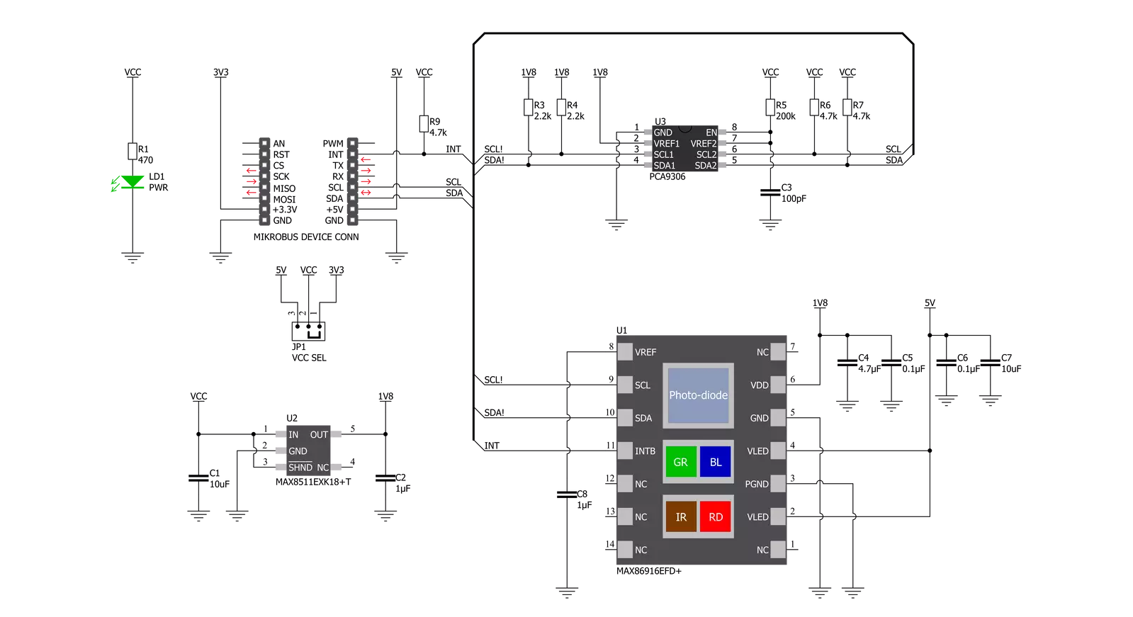
Heart Rate 10 Click is based on the MAX86916, a multipurpose optical sensor with applications in Heart Rate (HR) monitoring and as a medical-grade pulse oximeter from Analog Devices. The MAX86916 integrates four LED drivers and BLUE, GREEN, RED, and INFRARED LEDs. The LED current can be programmed from 0mA to 150mA, and the pulse width can be programmed from 70μs to 420μs to allow the algorithm to optimize data acquisition accuracy and power consumption based on use cases. Also, the MAX86916 includes a proximity function to save power and reduce visible light emission when the user’s finger is not on the sensor. The receive path in the MAX86916 is composed of an ambient-light-cancellation (ALC) circuit, a continuous-time sigma-delta ADC, and a proprietary digital filter that rejects slow-changing ambient light, including 100Hz/120Hz interference from
artificial lights. The ALC is designed to cancel ambient-light-generated photodiode current up to 200μA, allowing the sensor to work in high ambient light conditions. When the ambient light cancellation function reaches its maximum limit due to overflow from strong ambient light, the output of the ADC is affected, and the Ambient Light Cancellation Overflow interrupt, labeled as INT and routed on the INT pin of the mikroBUS™ socket, is generated to detect this condition. The MAX86916 does not require a specific Power-Up sequence but requires a supply voltage of 1.8V to work correctly. Therefore, a small regulating LDO, the MAX8511from Analog Devices, is used, providing a 1.8V out of both 5V and 3.3V mikroBUS™ rails. Heart Rate 10 Click communicates with MCU using the standard I2C 2-Wire interface with a maximum clock frequency of up to 400kHz.
It is fully adjustable through software registers, and the digital output data is stored in a 32-deep FIFO within the device. Since the sensor for operation requires a power supply of 1.8V, this Click board™ also features the PCA9306voltage-level translator from Texas Instruments. The I2C interface bus lines are routed to the dual bidirectional voltage-level translator, allowing this Click board™ to work properly with both 3.3V and 5V MCUs. This Click board™ can operate with either 3.3V or 5V logic voltage levels selected via the VCC SEL jumper. This way, both 3.3V and 5V capable MCUs can use the communication lines properly. However, the Click board™ comes equipped with a library containing easy-to-use functions and an example code that can be used, as a reference, for further development.


Features overview
Development board
UNI-DS v8 is a development board specially designed for the needs of rapid development of embedded applications. It supports a wide range of microcontrollers, such as different STM32, Kinetis, TIVA, CEC, MSP, PIC, dsPIC, PIC32, and AVR MCUs regardless of their number of pins, and a broad set of unique functions, such as the first-ever embedded debugger/programmer over WiFi. The development board is well organized and designed so that the end-user has all the necessary elements, such as switches, buttons, indicators, connectors, and others, in one place. Thanks to innovative manufacturing technology, UNI-DS v8 provides a fluid and immersive working experience, allowing access anywhere and under any
circumstances at any time. Each part of the UNI-DS v8 development board contains the components necessary for the most efficient operation of the same board. An advanced integrated CODEGRIP programmer/debugger module offers many valuable programming/debugging options, including support for JTAG, SWD, and SWO Trace (Single Wire Output)), and seamless integration with the Mikroe software environment. Besides, it also includes a clean and regulated power supply module for the development board. It can use a wide range of external power sources, including a battery, an external 12V power supply, and a power source via the USB Type-C (USB-C) connector. Communication options such as USB-UART, USB
HOST/DEVICE, CAN (on the MCU card, if supported), and Ethernet is also included. In addition, it also has the well-established mikroBUS™ standard, a standardized socket for the MCU card (SiBRAIN standard), and two display options for the TFT board line of products and character-based LCD. UNI-DS v8 is an integral part of the Mikroe ecosystem for rapid development. Natively supported by Mikroe software tools, it covers many aspects of prototyping and development thanks to a considerable number of different Click boards™ (over a thousand boards), the number of which is growing every day.

Microcontroller Overview
MCU Card / MCU
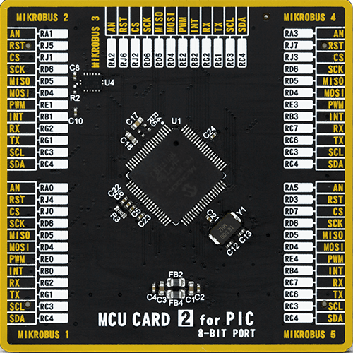
Type
8th Generation
Architecture
PIC
MCU Memory (KB)
128
Silicon Vendor
Microchip
Pin count
80
RAM (Bytes)
3862
Used MCU Pins
mikroBUS™ mapper
Take a closer look
Click board™ Schematic
Step by step
Project assembly

Start by selecting your development board and Click board™. Begin with the UNI-DS v8 as your development board.


Software Support
Library Description
This library contains API for Heart Rate 10 Click driver.
Key functions:
heartrate10_cfg_setup- Config Object Initialization function.heartrate10_init- Initialization function.heartrate10_default_cfg- Click Default Configuration function.
Open Source
Code example
The complete application code and a ready-to-use project are available through the NECTO Studio Package Manager for direct installation in the NECTO Studio. The application code can also be found on the MIKROE GitHub account.
/*!
 * @file main.c
 * @brief HeartRate10 Click example
 *
 * # Description
 * This example showcases ability for device to read Heart Rate with 4 different diodes.
 * There is IR, Red, Green and Blue. You can control every one of them individualy, and
 * change theirs sequence in FIFO register. All leds data is read from FIFO register,
 * it's 19bit data for every led.
 *
 * The demo application is composed of two sections :
 *
 * ## Application Init
 * Initialization of host communication periphrials and interrupt pin. Configures default
 * configuration to device where device is reset, checks Part ID and enables all 4 leds
 * and sets sequence as IR-Red-Green-Blue. Sets their power to maximum, and enables
 * interrupt on new data ready.
 *
 * ## Application Task
 * Reads FIFO data for all 4 didoes and logs them with separation character ','.
 *
 * @note
 * For testing this example application SerialPlot was used.
 * There you can see heart rate graphicly shown.
 *
 * @author Luka Filipovic
 *
 */

#include "board.h"
#include "log.h"
#include "heartrate10.h"

static heartrate10_t heartrate10;
static log_t logger;

void application_init ( void )
{
    log_cfg_t log_cfg;  /**< Logger config object. */
    heartrate10_cfg_t heartrate10_cfg;  /**< Click config object. */

    /**
     * Logger initialization.
     * Default baud rate: 115200
     * Default log level: LOG_LEVEL_DEBUG
     * @note If USB_UART_RX and USB_UART_TX
     * are defined as HAL_PIN_NC, you will
     * need to define them manually for log to work.
     * See @b LOG_MAP_USB_UART macro definition for detailed explanation.
     */
    LOG_MAP_USB_UART( log_cfg );
    log_init( &logger, &log_cfg );

    // Click initialization.
    heartrate10_cfg_setup( &heartrate10_cfg );
    HEARTRATE10_MAP_MIKROBUS( heartrate10_cfg, MIKROBUS_1 );
    if ( I2C_MASTER_ERROR == heartrate10_init( &heartrate10, &heartrate10_cfg ) )
    {
        log_error( &logger, " Initializtion." );
        log_info( &logger, " Please, run example again... " );

        for ( ; ; );
    }

    if ( HEARTRATE10_ERROR == heartrate10_default_cfg ( &heartrate10 ) )
    {
        log_error( &logger, " Configuration." );
        log_info( &logger, " Please, run example again... " );

        for ( ; ; );
    }
}

void application_task ( void )
{
    uint8_t rd_dat = 0;
    heartrate10_generic_read( &heartrate10, HEARTRATE10_REG_INT_STATUS, &rd_dat );
    if ( ( rd_dat & 0x40 ) )
    {
        uint32_t ir, red, green, blue = 0;
        heartrate10_read_complete_fifo_data( &heartrate10, &ir, &red, &green, &blue );
        log_printf( &logger, "%lu,%lu,%lu,%lu\r\n", ir, red, green, blue );
    }
    Delay_ms ( 3 );
}

int main ( void )
{
    /* Do not remove this line or clock might not be set correctly. */
    #ifdef PREINIT_SUPPORTED
    preinit();
    #endif

    application_init( );

    for ( ; ; )
    {
        application_task( );
    }

    return 0;
}

// ------------------------------------------------------------------------ END


