Upgrade your projects to the next level with STM32L496AG
Expand, connect, create!
Published Jul 22, 2025
Click board™
Terminal Click
Dev. board
Discovery kit with STM32L496AG MCU
Compiler
NECTO Studio
MCU
STM32L496AG
Experience seamless integration with our mikroBUS™ socket expansion solution, making your projects more versatile.
A
A
Hardware Overview
How does it work?
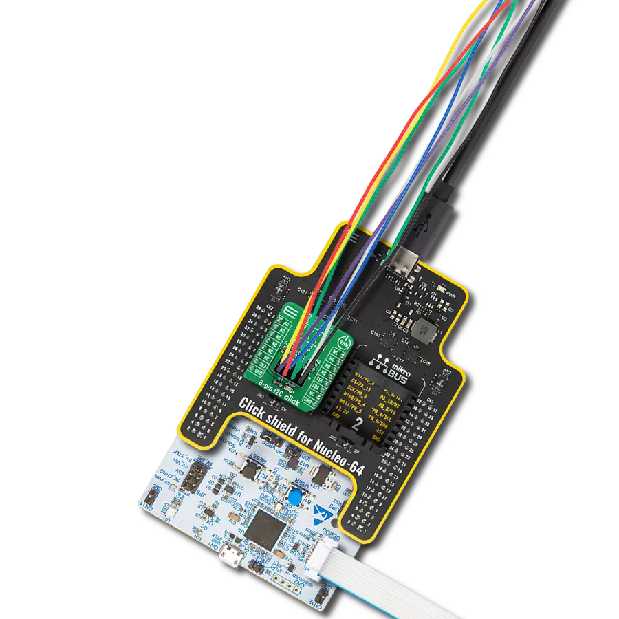
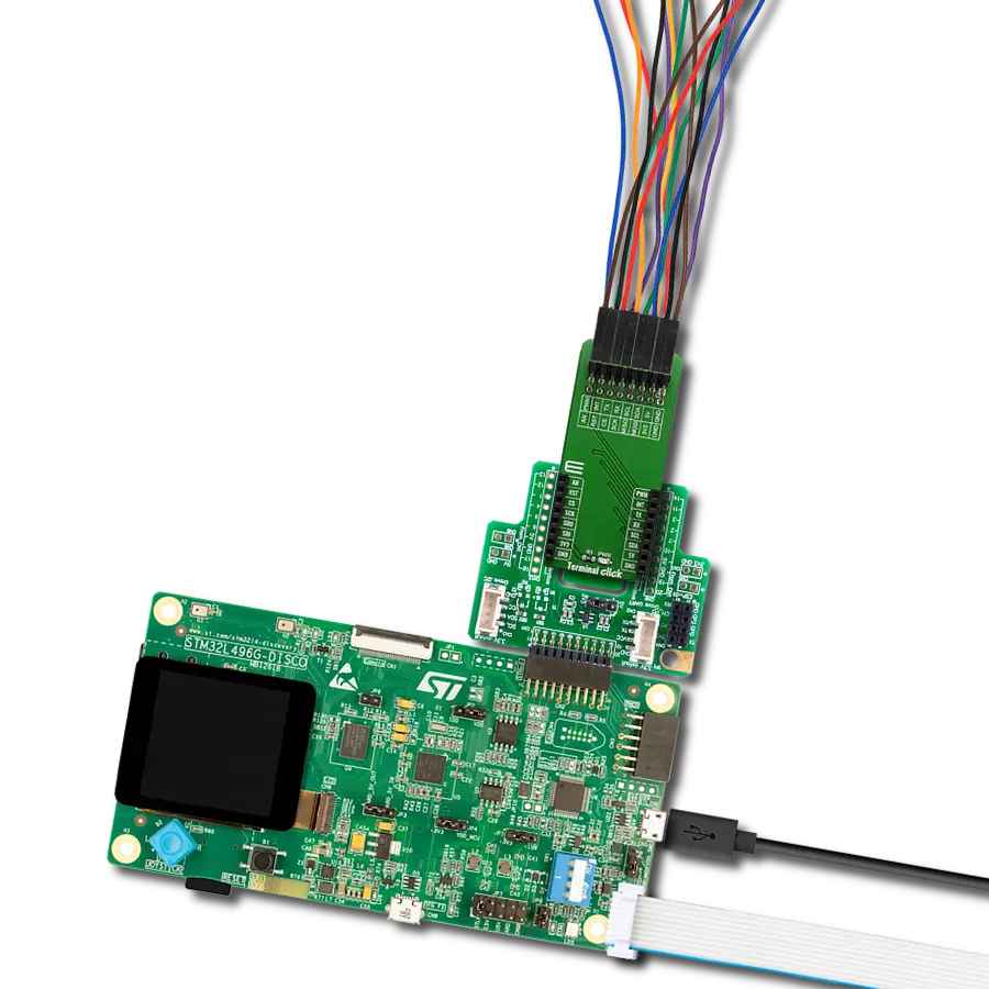
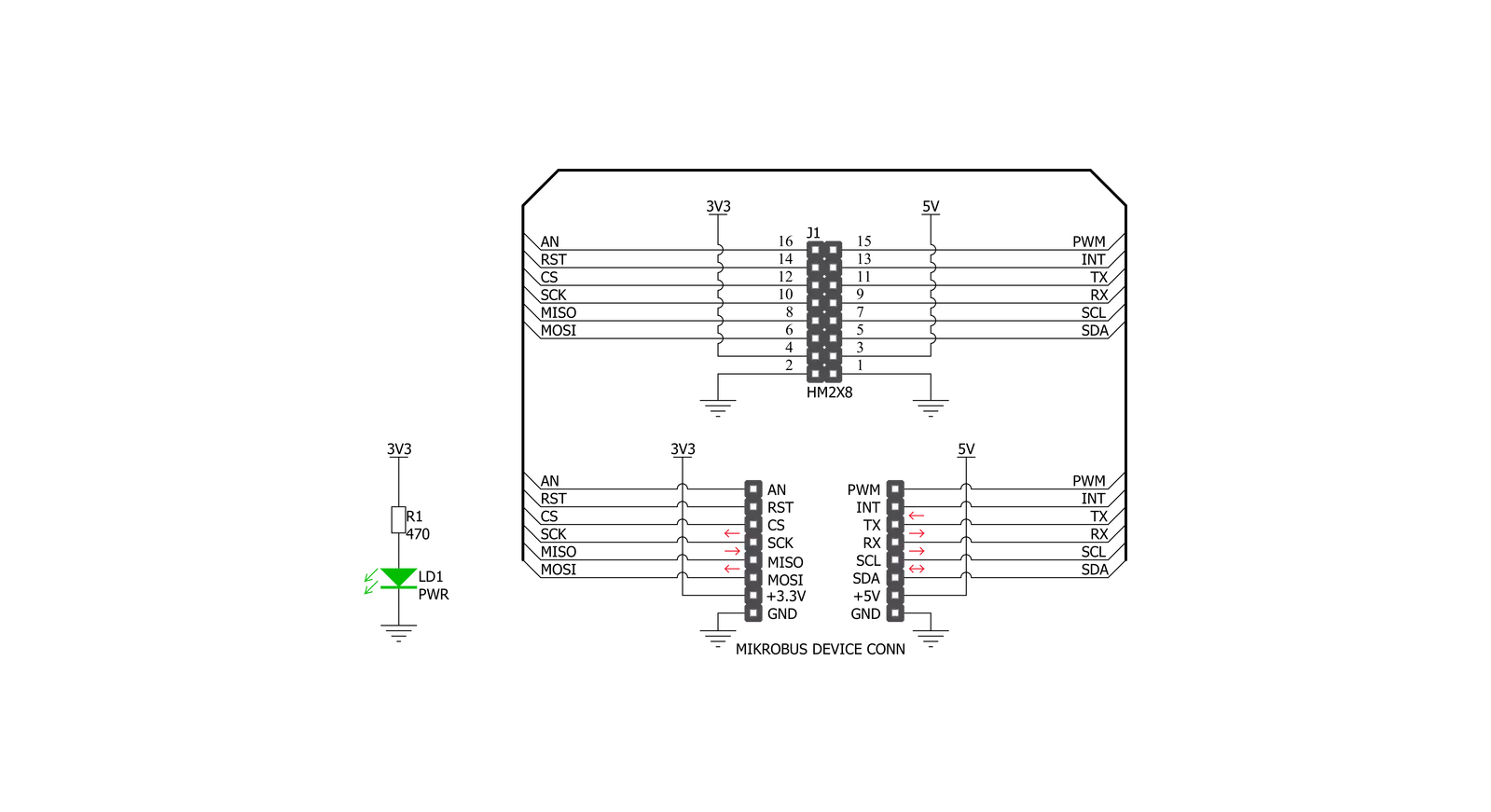
Terminal Click consists of a high-quality PCB that can be connected to the mikroBUS™ as any other click board. On the top of the Terminal click, a 2x8 pin header is placed. Each of the header pins is corresponding to a pin on the mikroBUS™ being used. These are simply wired in parallel. Thanks to the stacking headers, the connection with the click board™ remains firm and stable. Besides . Having this kind of stacking topology, allows for easy pin access and manipulation of the stacked click boards™, retaining a perfect connection quality at all times. When there's a need to attach
external equipment to the development system, the desired mikroBUS™ socket can be populated with Terminal click, allowing even more connections. This makes the stacking capacity almost unlimited. However, attention should be paid not to make the lines attached to the mikroBUS™ too long. In situations like this, the frequency of the communication might need to be stepped down a bit, in order to compensate for the longer mikroBUS™ signal lines. Lines of the mikroBUS™ to which Terminal click is attached, are shared through the top 16-pin header, which
mirrors pins of the connected mikroBUS™. Therefore, a care should be taken when working with the Terminal click and connecting an external device to it, because the same pins on the mikroBUS™ are shared, either for the communication (SPI, UART, I2C) or for some other purpose (RST, INT, or other pins used as GPIO). Since all the stacked click boards™ share the same power rails, a Terminal click also shares the power rails, which makes it compatible with any click board™ and development systems.

Features overview
Development board
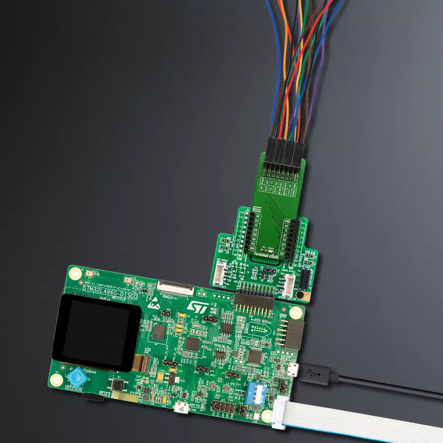
The 32L496GDISCOVERY Discovery kit serves as a comprehensive demonstration and development platform for the STM32L496AG microcontroller, featuring an Arm® Cortex®-M4 core. Designed for applications that demand a balance of high performance, advanced graphics, and ultra-low power consumption, this kit enables seamless prototyping for a wide range of embedded solutions. With its innovative energy-efficient
architecture, the STM32L496AG integrates extended RAM and the Chrom-ART Accelerator, enhancing graphics performance while maintaining low power consumption. This makes the kit particularly well-suited for applications involving audio processing, graphical user interfaces, and real-time data acquisition, where energy efficiency is a key requirement. For ease of development, the board includes an onboard ST-LINK/V2-1
debugger/programmer, providing a seamless out-of-the-box experience for loading, debugging, and testing applications without requiring additional hardware. The combination of low power features, enhanced memory capabilities, and built-in debugging tools makes the 32L496GDISCOVERY kit an ideal choice for prototyping advanced embedded systems with state-of-the-art energy efficiency.

Microcontroller Overview
MCU Card / MCU

Architecture
ARM Cortex-M4
MCU Memory (KB)
1024
Silicon Vendor
STMicroelectronics
Pin count
169
RAM (Bytes)
327680
Used MCU Pins
mikroBUS™ mapper
Take a closer look
Click board™ Schematic
Step by step
Project assembly

Start by selecting your development board and Click board™. Begin with the Discovery kit with STM32L496AG MCU as your development board.


Software Support
Library Description
This library contains API for Terminal Click driver.
Key functions:
terminal_set_pin_high- This function sets the output voltage on the specified pin to high.terminal_set_pin_low- This function sets the output voltage on the specified pin to low.
Open Source
Code example
The complete application code and a ready-to-use project are available through the NECTO Studio Package Manager for direct installation in the NECTO Studio. The application code can also be found on the MIKROE GitHub account.
/*!
 * \file
 * \brief Terminal Click example
 *
 * # Description
 * This example showcases how to initialize, configure and use the Terminal Click. It is a simple
 * GPIO Click which is used like an adapter for connecting and stacking other Clicks and external
 * equimpent.
 *
 * The demo application is composed of two sections :
 *
 * ## Application Init
 * This function initializes and configures the Click and logger modules.
 *
 * ## Application Task
 * This function sets the output on all the pins (one by one) on the left side to high, going
 * from top to bottom and then does the same with the ones on the right side, after which it
 * sets all pins to high and after one second sets them back to low.
 *
 * \author MikroE Team
 *
 */
// ------------------------------------------------------------------- INCLUDES

#include "board.h"
#include "log.h"
#include "terminal.h"

// ------------------------------------------------------------------ VARIABLES

static terminal_t terminal;
static log_t logger;

static digital_out_t *pin_addr[ 12 ] =
{
    &terminal.mosi,    // 0 MOSI
    &terminal.miso,    // 1 MISO
    &terminal.sck,     // 2 SCK
    &terminal.cs,      // 3 CS
    &terminal.rst,     // 4 RST
    &terminal.an,      // 5 AN
    &terminal.pwm,     // 6 PWM
    &terminal.int_pin, // 7 INT
    &terminal.tx_pin,  // 8 TX
    &terminal.rx_pin,  // 9 RX
    &terminal.scl,     // 10 SCL
    &terminal.sda      // 11 SDA
};

// ------------------------------------------------------- ADDITIONAL FUNCTIONS

static void blink ( digital_out_t *pin )
{
    terminal_set_pin_high( pin );
    Delay_100ms( );
    terminal_set_pin_low( pin );
}

static void all_on ( )
{
   int i;

   for( i = 0; i < 12; i++ )
   {
        terminal_set_pin_high( pin_addr[ i ] );
   }
}

static void all_off ( )
{
   int i;

   for( i = 0; i < 12; i++ )
   {
        terminal_set_pin_low( pin_addr[ i ] );
   }
}

// ------------------------------------------------------ APPLICATION FUNCTIONS

void application_init ( )
{
    log_cfg_t log_cfg;
    terminal_cfg_t cfg;

    /**
     * Logger initialization.
     * Default baud rate: 115200
     * Default log level: LOG_LEVEL_DEBUG
     * @note If USB_UART_RX and USB_UART_TX
     * are defined as HAL_PIN_NC, you will
     * need to define them manually for log to work.
     * See @b LOG_MAP_USB_UART macro definition for detailed explanation.
     */
    LOG_MAP_USB_UART( log_cfg );
    log_init( &logger, &log_cfg );
    log_info(&logger, "---- Application Init ----");

    //  Click initialization.

    terminal_cfg_setup( &cfg );
    TERMINAL_MAP_MIKROBUS( cfg, MIKROBUS_1 );
    terminal_init( &terminal, &cfg );
}

void application_task ( )
{
    int i;

    for( i = 0; i < 12; i++ )
    {
        blink( pin_addr[ i ] );
    }

    all_on( );
    Delay_1sec( );
    all_off( );
}

int main ( void )
{
    /* Do not remove this line or clock might not be set correctly. */
    #ifdef PREINIT_SUPPORTED
    preinit();
    #endif

    application_init( );

    for ( ; ; )
    {
        application_task( );
    }

    return 0;
}

// ------------------------------------------------------------------------ END
Additional Support
Resources
Category:Adapter