Manage various sensors and actuators with our I2C adapter and PIC32MZ2048EFM100
One Click to rule them all: Uniting devices on a single bus

Published Nov 11, 2023
Click board™
8-pin I2C Click
Dev. board
Curiosity PIC32 MZ EF
Compiler
NECTO Studio
MCU
PIC32MZ2048EFM100
This innovative product unlocks new possibilities in I2C connectivity, inspiring users to explore and unleash the full potential of 8-pin connections, fostering innovation and creativity in electronics projects.
A
A
Hardware Overview
How does it work?
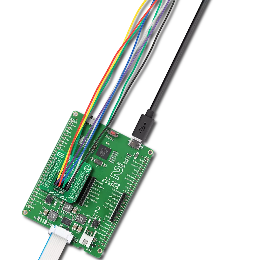
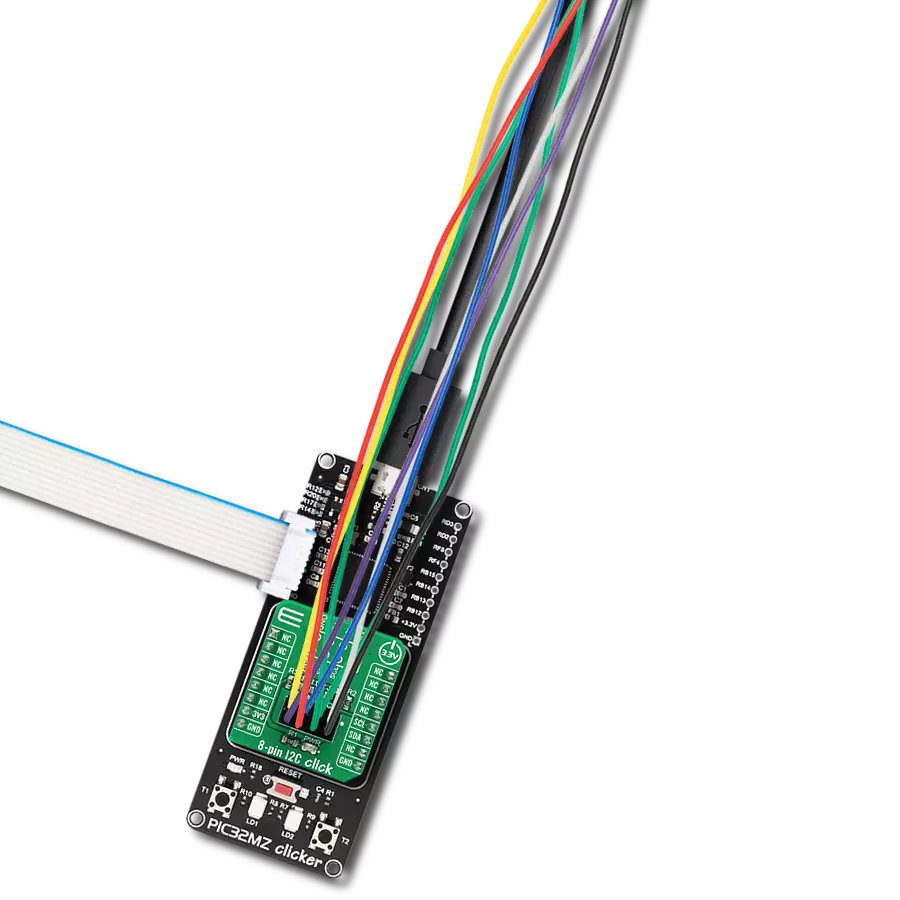
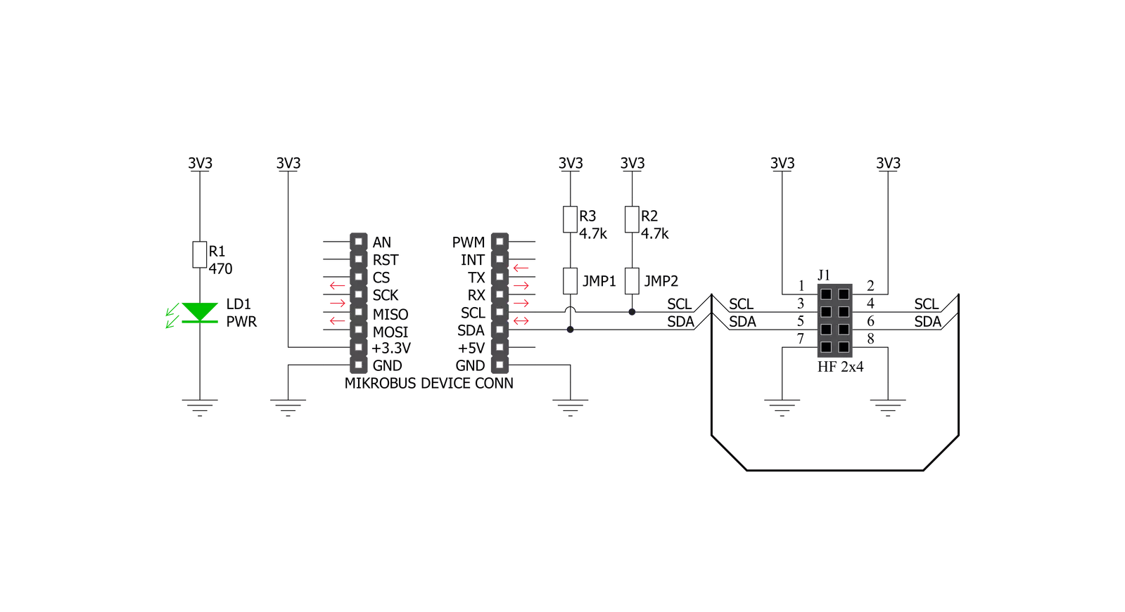
8-pin I2C Click is an adapter Click board™ that simplifies the connection of add-on boards to the mikroBUS™ socket. This Click board™ represents a small-size PCB that can be connected to the mikroBUS™ socket like any other Click board™, with a 2x4 female header placed on itself. Each header pin corresponds to a pin on the mikroBUS™ socket, such as I2C lines (SCL, SDA) with two jumpers for I2C lines pull-up function selection, 3V3 power supply, and ground. This Click board™ allows easy pin access and manipulation while always retaining a perfect connection
quality. Being compatible with Apple's MFI is the most important feature of the 8-pin I2C Click board™, which ensures its proper operation with additional Apple accessories. The name is a shortened version of the long-form Made for iPod, the original program that ultimately became MFI which refers to peripherals that work with Apple's iPod, iPad, and iPhone. 8-pin I2C Click communicates with MCU using the standard I2C 2-Wire interface. Lines of the mikroBUS™ to which this Click board™ is attached are shared through the top 8-pin female header, which mirrors
the pins of the connected mikroBUS™ socket. The 8-pin I2C Click also shares the 3V3 power rails, making it compatible with other power-compatible Click board™ and development systems. This Click board™ can only be operated with a 3.3V logic voltage level. The board must perform appropriate logic voltage level conversion before using MCUs with different logic levels. However, the Click board™ comes equipped with a library containing functions and an example code that can be used as a reference for further development.

Features overview
Development board
Curiosity PIC32 MZ EF development board is a fully integrated 32-bit development platform featuring the high-performance PIC32MZ EF Series (PIC32MZ2048EFM) that has a 2MB Flash, 512KB RAM, integrated FPU, Crypto accelerator, and excellent connectivity options. It includes an integrated programmer and debugger, requiring no additional hardware. Users can expand
functionality through MIKROE mikroBUS™ Click™ adapter boards, add Ethernet connectivity with the Microchip PHY daughter board, add WiFi connectivity capability using the Microchip expansions boards, and add audio input and output capability with Microchip audio daughter boards. These boards are fully integrated into PIC32’s powerful software framework, MPLAB Harmony,
which provides a flexible and modular interface to application development a rich set of inter-operable software stacks (TCP-IP, USB), and easy-to-use features. The Curiosity PIC32 MZ EF development board offers expansion capabilities making it an excellent choice for a rapid prototyping board in Connectivity, IOT, and general-purpose applications.

Microcontroller Overview
MCU Card / MCU

Architecture
PIC32
MCU Memory (KB)
2048
Silicon Vendor
Microchip
Pin count
100
RAM (Bytes)
524288
Used MCU Pins
mikroBUS™ mapper
Take a closer look
Click board™ Schematic
Step by step
Project assembly

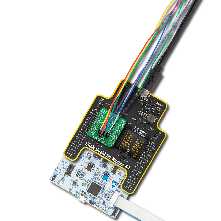
Start by selecting your development board and Click board™. Begin with the Curiosity PIC32 MZ EF as your development board.


Software Support
Library Description
This library contains API for 8-pin I2C Click driver.
Key functions:
c8pini2c_generic_write- Generic write function.c8pini2c_generic_read- Generic read function.
Open Source
Code example
The complete application code and a ready-to-use project are available through the NECTO Studio Package Manager for direct installation in the NECTO Studio. The application code can also be found on the MIKROE GitHub account.
/*!
 * \file
 * \brief 8pinI2c Click example
 *
 * # Description
 * This demo example reads temperature detected by Surface temp Click board.
 *
 * The demo application is composed of two sections :
 *
 * ## Application Init
 * Initializes the driver and configures a Surface temp Click board.
 *
 * ## Application Task
 * Reads the temperature detected by Surface temp Click board and
 * logs it on the USB UART each second.
 *
 * @note
 * In order to run this example successfully, a Surface temp Click board needs to be
 * connected properly to an 8-pin I2C Click board.
 *
 * \author MikroE Team
 *
 */
// ------------------------------------------------------------------- INCLUDES

#include "board.h"
#include "log.h"
#include "c8pini2c.h"

// ------------------------------------------------------------------ VARIABLES

static c8pini2c_t c8pini2c;
static log_t logger;

// Surface temp Click - example
#define SURFACE_TEMP_DEVICE_SLAVE_ADDRESS 0x48
#define SURFACE_TEMP_REG_SOFT_RESET       0x2F
#define SURFACE_TEMP_REG_ID               0x0B
#define SURFACE_TEMP_REG_CONFIG           0x03
#define SURFACE_TEMP_REG_TEMP_MSB         0x00

// ------------------------------------------------------- ADDITIONAL FUNCTIONS

void surfacetemp_soft_reset (  )
{
    uint8_t tx_data;

    tx_data = SURFACE_TEMP_REG_SOFT_RESET;

    c8pini2c_generic_write ( &c8pini2c, SURFACE_TEMP_DEVICE_SLAVE_ADDRESS,
                                        0, &tx_data, 1 );
}

uint8_t surfacetemp_setup (  )
{
    uint8_t tmp;

    surfacetemp_soft_reset( );
    Delay_100ms( );
    c8pini2c_generic_read( &c8pini2c, SURFACE_TEMP_DEVICE_SLAVE_ADDRESS,
                                      SURFACE_TEMP_REG_ID, &tmp, 1 );

    if ( tmp != 0xCB )
    {
        return 1;
    }
    tmp = 0x93;
    c8pini2c_generic_write( &c8pini2c, SURFACE_TEMP_DEVICE_SLAVE_ADDRESS,
                                       SURFACE_TEMP_REG_CONFIG, &tmp, 1 );

    return 0;
}

float surfacetemp_get_temperature (  )
{
    uint8_t rx_buff[ 2 ];
    int16_t temp;
    float temperature;

    c8pini2c_generic_read( &c8pini2c, SURFACE_TEMP_DEVICE_SLAVE_ADDRESS,
                                      SURFACE_TEMP_REG_TEMP_MSB, &rx_buff[ 0 ], 2 );

    temp = rx_buff[ 0 ];
    temp <<= 8;
    temp |= rx_buff[ 1 ];
    temp &= 0xFFF8;

    temperature = (float)(temp);
    temperature *= 0.0078;

    return temperature;
}

// ------------------------------------------------------ APPLICATION FUNCTIONS

void application_init ( void )
{
    log_cfg_t log_cfg;
    c8pini2c_cfg_t cfg;

    uint8_t status;

    /**
     * Logger initialization.
     * Default baud rate: 115200
     * Default log level: LOG_LEVEL_DEBUG
     * @note If USB_UART_RX and USB_UART_TX
     * are defined as HAL_PIN_NC, you will
     * need to define them manually for log to work.
     * See @b LOG_MAP_USB_UART macro definition for detailed explanation.
     */
    LOG_MAP_USB_UART( log_cfg );
    log_init( &logger, &log_cfg );
    log_info( &logger, "---- Application Init ----" );

    //  Click initialization.

    c8pini2c_cfg_setup( &cfg );
    C8PINI2C_MAP_MIKROBUS( cfg, MIKROBUS_1 );
    c8pini2c_init( &c8pini2c, &cfg );

    status = surfacetemp_setup( );
    if ( status == 0 )
    {
        log_printf( &logger, "--- INIT DONE --- \r\n" );
    }
    else
    {
        log_printf( &logger, "--- INIT ERROR --- \r\n" );
        for( ; ; );
    }
}

void application_task ( void )
{
    float temperature;

    temperature = surfacetemp_get_temperature( );
    log_printf( &logger, "> Temperature : %.2f Celsius\r\n", temperature );
    Delay_ms ( 1000 );
}

int main ( void )
{
    /* Do not remove this line or clock might not be set correctly. */
    #ifdef PREINIT_SUPPORTED
    preinit();
    #endif

    application_init( );

    for ( ; ; )
    {
        application_task( );
    }

    return 0;
}

// ------------------------------------------------------------------------ END