Ensure stable and consistent voltage references with MCP1541 and TM4C129ENCPDT
Precision in a digital world
Published Sep 30, 2023
Click board™
DigiVref Click
Dev. board
Fusion for Tiva v8
Compiler
NECTO Studio
MCU
TM4C129ENCPDT
From integrated circuits to sensor networks, our digital reference voltage solution empowers users to achieve voltage precision in the digital realm, setting a new benchmark for digital reference generation
A
A
Hardware Overview
How does it work?
DigiVref Click is based on the MCP1541, a precise voltage reference IC by Microchip is used to provide an accurate voltage output. However, this IC is very prone to voltage drop when loaded, so even a small load of 2mA may cause a voltage drop at its output. Therefore, an operational amplifier with a unity gain is used as a buffer. The voltage reference output of 4.096V (VREF) is routed to a common pin of the CD74HC4051, an analog multiplexer/demultiplexer IC, by Texas Instruments. This circuit has a one-to-eight internal switch with a digitally selected position. The position of the switch can be selected by applying logic levels to pins S0 to S2. Four outputs of the CD74HC4051 are routed to a voltage divider circuit composed of four 10K resistors. By routing the VREF across the voltage divider, one of four output voltage reference values can be selected,
depending on the selected switch position. The output voltage (VOUT) can be set to one of the following values: 1.024V, 2.048V, 3.072V, and 4.096V. The CD74HC4051 is controlled by the SN74HC595, an 8-bit shift register IC with tri-state output registers, by Texas Instruments. The SN74HC595 allows the data to be shifted in and then latched at the output. The state of the output pins will not change, as long as there is no new data shifted in and latched to the parallel output register (or as long as the #OE pin stays LOW, but it is hardwired to the GND on this Click board™). This allows the Click board™ to be completely independent on the SPI interface, even if it is disconnected at some point. Once set, the selected reference voltage will be available at the VOUT connector (standard 1x2-pin header with 2.54mm pitch), as long as the Click board™ is
powered. There are two control pins available on the CD74HC4051 since there are only 4 valid positions. Control pin S2 is grounded, so the CD74HC4051 is controlled by means of two pins: S0 and S1. These pins are routed to Q1 and Q2 outputs of the SN74HC595 IC. The SN74HC595 IC is controlled over the SPI interface, with its pins routed to the respective mikroBUS™ pins (CS, MOSI, SCK). Note that SPI data values that set pins other than Q1 and Q2, will not have any effect on this Click board™. Besides the VOUT connector, the VOUT voltage is also routed to the AN pin of the mikroBUS™, allowing it to be used by the host MCU. Therefore, a note should be taken that the Click board™ is not intended to be used with 3.3V MCUs, especially if they do not have 5V tolerant pins. To use the Click board™ with 3.3V MCUs, a proper level shifting circuit must be used.


Features overview
Development board
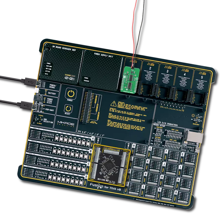
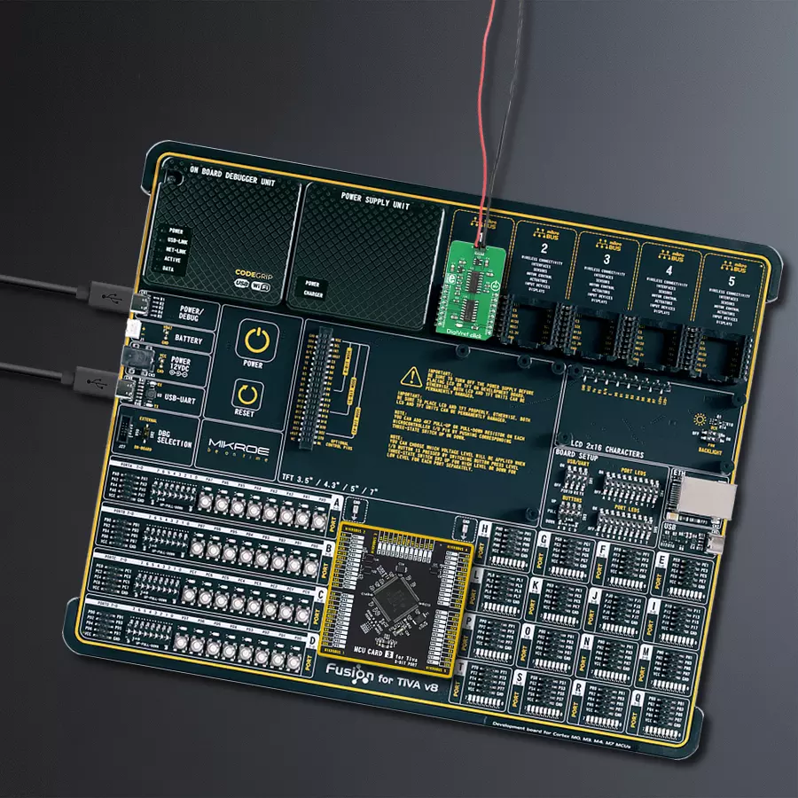
Fusion for TIVA v8 is a development board specially designed for the needs of rapid development of embedded applications. It supports a wide range of microcontrollers, such as different 32-bit ARM® Cortex®-M based MCUs from Texas Instruments, regardless of their number of pins, and a broad set of unique functions, such as the first-ever embedded debugger/programmer over a WiFi network. The development board is well organized and designed so that the end-user has all the necessary elements, such as switches, buttons, indicators, connectors, and others, in one place. Thanks to innovative manufacturing technology, Fusion for TIVA v8 provides a fluid and immersive working experience, allowing access
anywhere and under any circumstances at any time. Each part of the Fusion for TIVA v8 development board contains the components necessary for the most efficient operation of the same board. An advanced integrated CODEGRIP programmer/debugger module offers many valuable programming/debugging options, including support for JTAG, SWD, and SWO Trace (Single Wire Output)), and seamless integration with the Mikroe software environment. Besides, it also includes a clean and regulated power supply module for the development board. It can use a wide range of external power sources, including a battery, an external 12V power supply, and a power source via the USB Type-C (USB-C) connector.
Communication options such as USB-UART, USB HOST/DEVICE, CAN (on the MCU card, if supported), and Ethernet is also included. In addition, it also has the well-established mikroBUS™ standard, a standardized socket for the MCU card (SiBRAIN standard), and two display options for the TFT board line of products and character-based LCD. Fusion for TIVA v8 is an integral part of the Mikroe ecosystem for rapid development. Natively supported by Mikroe software tools, it covers many aspects of prototyping and development thanks to a considerable number of different Click boards™ (over a thousand boards), the number of which is growing every day.

Microcontroller Overview
MCU Card / MCU

Type
8th Generation
Architecture
ARM Cortex-M4
MCU Memory (KB)
1024
Silicon Vendor
Texas Instruments
Pin count
128
RAM (Bytes)
262144
Used MCU Pins
mikroBUS™ mapper
Take a closer look
Click board™ Schematic

Step by step
Project assembly

Start by selecting your development board and Click board™. Begin with the Fusion for Tiva v8 as your development board.


Track your results in real time
Application Output
1. Application Output - In Debug mode, the 'Application Output' window enables real-time data monitoring, offering direct insight into execution results. Ensure proper data display by configuring the environment correctly using the provided tutorial.

2. UART Terminal - Use the UART Terminal to monitor data transmission via a USB to UART converter, allowing direct communication between the Click board™ and your development system. Configure the baud rate and other serial settings according to your project's requirements to ensure proper functionality. For step-by-step setup instructions, refer to the provided tutorial.

3. Plot Output - The Plot feature offers a powerful way to visualize real-time sensor data, enabling trend analysis, debugging, and comparison of multiple data points. To set it up correctly, follow the provided tutorial, which includes a step-by-step example of using the Plot feature to display Click board™ readings. To use the Plot feature in your code, use the function: plot(*insert_graph_name*, variable_name);. This is a general format, and it is up to the user to replace 'insert_graph_name' with the actual graph name and 'variable_name' with the parameter to be displayed.

Software Support
Library Description
This library contains API for DigiVref Click driver.
Key functions:
digivref_set_output_voltage- This function sets reference output voltage
Open Source
Code example
The complete application code and a ready-to-use project are available through the NECTO Studio Package Manager for direct installation in the NECTO Studio. The application code can also be found on the MIKROE GitHub account.
/*!
 * \file
 * \brief DigiVref Click example
 *
 * # Description
 * This app changes the reference output voltage.
 *
 * The demo application is composed of two sections :
 *
 * ## Application Init
 * Initialization device.
 *
 * ## Application Task
 * Changes the reference output voltage every 3 seconds.
 *
 * \author MikroE Team
 *
 */
// ------------------------------------------------------------------- INCLUDES

#include "board.h"
#include "log.h"
#include "digivref.h"

// ------------------------------------------------------------------ VARIABLES

static digivref_t digivref;
static log_t logger;

// ------------------------------------------------------ APPLICATION FUNCTIONS

void application_init ( void )
{
    log_cfg_t log_cfg;
    digivref_cfg_t cfg;

    /**
     * Logger initialization.
     * Default baud rate: 115200
     * Default log level: LOG_LEVEL_DEBUG
     * @note If USB_UART_RX and USB_UART_TX
     * are defined as HAL_PIN_NC, you will
     * need to define them manually for log to work.
     * See @b LOG_MAP_USB_UART macro definition for detailed explanation.
     */
    LOG_MAP_USB_UART( log_cfg );
    log_init( &logger, &log_cfg );
    log_info( &logger, "---- Application Init ----" );

    //  Click initialization.

    digivref_cfg_setup( &cfg );
    DIGIVREF_MAP_MIKROBUS( cfg, MIKROBUS_1 );
    digivref_init( &digivref, &cfg );
}

void application_task ( void )
{
    digivref_set_output_voltage( &digivref, DIGIVREF_REF_VOLTAGE_4096mV );
    Delay_ms ( 1000 );
    Delay_ms ( 1000 );
    Delay_ms ( 1000 );
    digivref_set_output_voltage(  &digivref, DIGIVREF_REF_VOLTAGE_3072mV );
    Delay_ms ( 1000 );
    Delay_ms ( 1000 );
    Delay_ms ( 1000 );
    digivref_set_output_voltage( &digivref, DIGIVREF_REF_VOLTAGE_2048mV );
    Delay_ms ( 1000 );
    Delay_ms ( 1000 );
    Delay_ms ( 1000 );
    digivref_set_output_voltage( &digivref, DIGIVREF_REF_VOLTAGE_1024mV );
    Delay_ms ( 1000 );
    Delay_ms ( 1000 );
    Delay_ms ( 1000 );
    digivref_set_output_voltage( &digivref, DIGIVREF_REF_VOLTAGE_2048mV );
    Delay_ms ( 1000 );
    Delay_ms ( 1000 );
    Delay_ms ( 1000 );
    digivref_set_output_voltage( &digivref, DIGIVREF_REF_VOLTAGE_3072mV );
    Delay_ms ( 1000 );
    Delay_ms ( 1000 );
    Delay_ms ( 1000 );
}

int main ( void )
{
    /* Do not remove this line or clock might not be set correctly. */
    #ifdef PREINIT_SUPPORTED
    preinit();
    #endif

    application_init( );

    for ( ; ; )
    {
        application_task( );
    }

    return 0;
}

// ------------------------------------------------------------------------ END


