Expand LIN bus communication capabilities in vehicle sensor networks and other similar systems with MCP2003B and TM4C129ENCZAD
Physical interface for LIN bus systems widely used in vehicles and industrial settings

Published Mar 09, 2024
Click board™
MCP2003B Click
Dev. board
Fusion for Tiva v8
Compiler
NECTO Studio
MCU
TM4C129ENCZAD
Achieve communication within automotive and industrial environments through the LIN (Local Interconnect Network) bus system
A
A
Hardware Overview
How does it work?
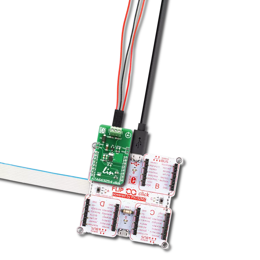
MCP2003B Click is based on the MCP2003B, a LIN transceiver from Microchip. This transceiver has both short-circuit and overtemperature protection by internal circuitry. It is designed to operate in an automotive environment and will work in specified transient conditions while meeting all stringent quiescent requirements. The MCP2003B has very high electromagnetic immunity (EMI), 60V load dump protection, high electrostatic discharge (ESD) immunity without TVS, and very high immunity to RF disturbances. It also can work in low-power mode and has an automatic thermal shutdown. One of the protections is direct capacitor coupling robustness without transient voltage suppressor (TVS) of ±35V and ±85V on LBUS, ground loss protection, reverse supply protection, and many more. The MCP2003B Click has four operational modes: Power-Down mode, Ready mode, Operation mode, and Transmitter OFF mode. In Power-Down mode, the lowest power mode, everything except the wake-up pin (LWK on an unpopulated header) is shut down. LIN Bus activity typically changes the device from Power-down to Ready mode in 70μs. In Ready mode, the receiver
is powered up and is ready to receive data while the transmitter is disabled. In Operational mode, all internal modules are operational. The Transmitter OFF mode is reached whenever the transmitter is disabled due to a fault condition, for example, if there is a thermal overload, bus contention, RSD monitoring, and TXD timer expiration. For the typical application as a Master node, the MCP2003B requires the LBUS line of the chip to be connected to the VBB of the LIN BUS, achievable via a populated L-PULL jumper. This jumper can be removed in other scenarios, such as the LIN Slave node. To communicate with the host MCU, the MCP2003B uses a UART interface with commonly used UART RX and TX pins as its default communication protocol to transmit and exchange data. The RX pin is internally monitored and must be at a high level, while LBUS is recessive in Operation mode. Otherwise, an internal fault will be created, and the device will transition to Transmitter Off mode. A voltage regulator sensing circuit, comprised of an MCP1804 regulator and controlled via MCP2003B itself, is connected to the RX pin and internally monitors the RX pin when the LBUS
line is recessive (RX is in a high logic state). If the RX pin is left open, it will not allow the device to switch (or stay) in Operation Mode. That’s why the RX pin is connected to a valid supply, provided by the voltage regulator, through a pull-up 2.2kΩ resistor. A CS SEL jumper can be used to set the chip select pin of the MCP2003B permanently connected to a logic HIGH (set by default), thus enabled all the time, or that the MCU performs this function via the CS of the mikroBUS™ socket. The extra pins LWK (CS on mikroBUS™ socket), CS (Wake-up pin on MCP2003B), TX, and RX are also available above the mikroBUS™ and can be used for external control. The wake-up from power-down mode can be controlled only through the LWK pin of this header. The RXD, TXD, CS, and LWK pins tolerate high voltage. This Click board™ can be operated only with a 3.3V logic voltage level. The board must perform appropriate logic voltage level conversion before using MCUs with different logic levels. However, the Click board™ comes equipped with a library containing functions and an example code that can be used as a reference for further development.

Features overview
Development board
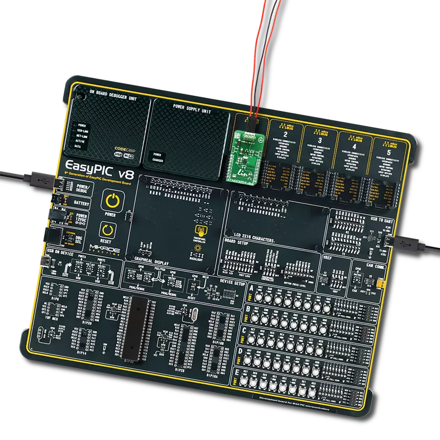
Fusion for TIVA v8 is a development board specially designed for the needs of rapid development of embedded applications. It supports a wide range of microcontrollers, such as different 32-bit ARM® Cortex®-M based MCUs from Texas Instruments, regardless of their number of pins, and a broad set of unique functions, such as the first-ever embedded debugger/programmer over a WiFi network. The development board is well organized and designed so that the end-user has all the necessary elements, such as switches, buttons, indicators, connectors, and others, in one place. Thanks to innovative manufacturing technology, Fusion for TIVA v8 provides a fluid and immersive working experience, allowing access
anywhere and under any circumstances at any time. Each part of the Fusion for TIVA v8 development board contains the components necessary for the most efficient operation of the same board. An advanced integrated CODEGRIP programmer/debugger module offers many valuable programming/debugging options, including support for JTAG, SWD, and SWO Trace (Single Wire Output)), and seamless integration with the Mikroe software environment. Besides, it also includes a clean and regulated power supply module for the development board. It can use a wide range of external power sources, including a battery, an external 12V power supply, and a power source via the USB Type-C (USB-C) connector.
Communication options such as USB-UART, USB HOST/DEVICE, CAN (on the MCU card, if supported), and Ethernet is also included. In addition, it also has the well-established mikroBUS™ standard, a standardized socket for the MCU card (SiBRAIN standard), and two display options for the TFT board line of products and character-based LCD. Fusion for TIVA v8 is an integral part of the Mikroe ecosystem for rapid development. Natively supported by Mikroe software tools, it covers many aspects of prototyping and development thanks to a considerable number of different Click boards™ (over a thousand boards), the number of which is growing every day.

Microcontroller Overview
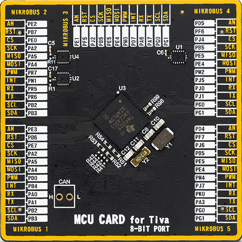
MCU Card / MCU
Type
8th Generation
Architecture
ARM Cortex-M4
MCU Memory (KB)
1024
Silicon Vendor
Texas Instruments
Pin count
212
RAM (Bytes)
262144
Used MCU Pins
mikroBUS™ mapper
Take a closer look
Click board™ Schematic

Step by step
Project assembly

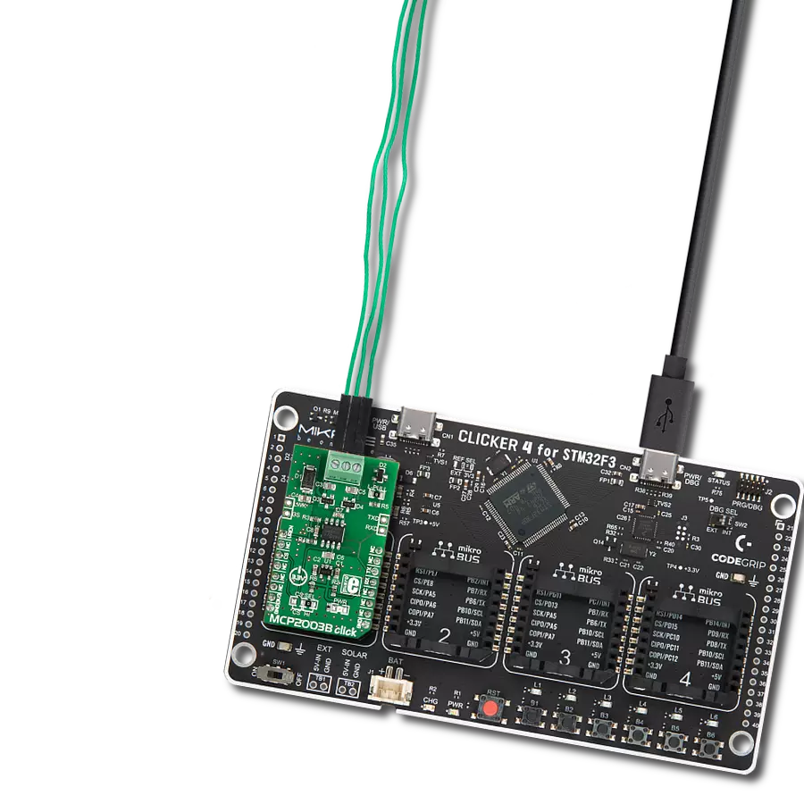
Start by selecting your development board and Click board™. Begin with the Fusion for Tiva v8 as your development board.


Software Support
Library Description
This library contains API for MCP2003B Click driver.
Key functions:
mcp2003b_generic_write- This function writes a desired number of data bytes by using UART serial interfacemcp2003b_generic_read- This function reads a desired number of data bytes by using UART serial interfacemcp2003b_set_cs_pin- This function sets the chip select (CS) pin logic state
Open Source
Code example
The complete application code and a ready-to-use project are available through the NECTO Studio Package Manager for direct installation in the NECTO Studio. The application code can also be found on the MIKROE GitHub account.
/*!
 * @file main.c
 * @brief MCP2003B Click Example.
 *
 * # Description
 * This example demonstrates the use of an MCP2003B Click board by showing
 * the communication between the two Click board configured as a receiver and transmitter.
 *
 * The demo application is composed of two sections :
 *
 * ## Application Init
 * Initializes the driver and logger and displays the selected application mode.
 *
 * ## Application Task
 * Depending on the selected mode, it reads all the received data or
 * sends the desired message every 3 seconds.
 *
 * @note
 * The Click boards should be connected as follows: VBB->VBB, LBUS->LBUS, GND->GND.
 * The communication power supply voltage provided on VBB pin should be in range from 5.5V to 30V.

 * @author Stefan Filipovic
 *
 */

#include "board.h"
#include "log.h"
#include "mcp2003b.h"

// Comment out the line below in order to switch the application mode to receiver
#define DEMO_APP_TRANSMITTER

#define DEMO_TEXT_MESSAGE   "MIKROE - MCP2003B Click board\r\n"

static mcp2003b_t mcp2003b;
static log_t logger;

void application_init ( void )
{
    log_cfg_t log_cfg;  /**< Logger config object. */
    mcp2003b_cfg_t mcp2003b_cfg;  /**< Click config object. */

    /**
     * Logger initialization.
     * Default baud rate: 115200
     * Default log level: LOG_LEVEL_DEBUG
     * @note If USB_UART_RX and USB_UART_TX
     * are defined as HAL_PIN_NC, you will
     * need to define them manually for log to work.
     * See @b LOG_MAP_USB_UART macro definition for detailed explanation.
     */
    LOG_MAP_USB_UART( log_cfg );
    log_init( &logger, &log_cfg );
    log_info( &logger, " Application Init " );

    // Click initialization.
    mcp2003b_cfg_setup( &mcp2003b_cfg );
    MCP2003B_MAP_MIKROBUS( mcp2003b_cfg, MIKROBUS_1 );
    if ( UART_ERROR == mcp2003b_init( &mcp2003b, &mcp2003b_cfg ) )
    {
        log_error( &logger, " Communication init." );
        for ( ; ; );
    }
#ifdef DEMO_APP_TRANSMITTER
    log_printf( &logger, " Application Mode: Transmitter\r\n" );
#else
    log_printf( &logger, " Application Mode: Receiver\r\n" );
#endif
    log_info( &logger, " Application Task " );
}

void application_task ( void )
{
#ifdef DEMO_APP_TRANSMITTER
    mcp2003b_generic_write( &mcp2003b, DEMO_TEXT_MESSAGE, strlen( DEMO_TEXT_MESSAGE ) );
    log_printf( &logger, "%s", ( char * ) DEMO_TEXT_MESSAGE );
    Delay_ms ( 1000 );
    Delay_ms ( 1000 );
    Delay_ms ( 1000 );
#else
    uint8_t rx_data = 0;
    if ( mcp2003b_generic_read( &mcp2003b, &rx_data, 1 ) > 0 )
    {
        log_printf( &logger, "%c", rx_data );
    }
#endif
}

int main ( void )
{
    /* Do not remove this line or clock might not be set correctly. */
    #ifdef PREINIT_SUPPORTED
    preinit();
    #endif

    application_init( );

    for ( ; ; )
    {
        application_task( );
    }

    return 0;
}

// ------------------------------------------------------------------------ END