Make your temperature measurements more reliable and efficient with MCP9600 and STM32F412RE
K-Type connection: Your path to perfect temperature control

Published Nov 02, 2023
Click board™
Thermo K Click
Dev. board
Fusion for ARM v8
Compiler
NECTO Studio
MCU
STM32F412RE
Our cutting-edge solution serves as a K-Type thermocouple probe interface, offering unparalleled accuracy and control for all your temperature measurement needs
A
A
Hardware Overview
How does it work?
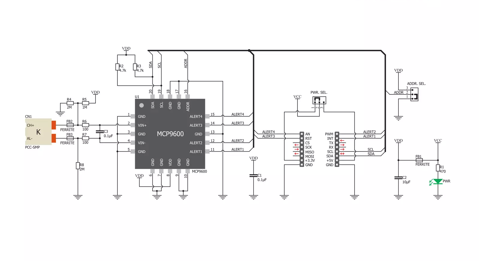
Thermo K Click is based on the MCP9600, a thermocouple EMF to temperature converter from Microchip. This converter typically has an accuracy of ±0.5°C for thermocouple hot-junction with very good hot and cold-junctions resolution of +0.0625°C. It features four programmable temperature alert outputs that monitor hot or cold-junction temperature, detects rising or falling temperature, and has up to 255°C of programmable hysteresis. In addition, it comes with integrated cold-junction compensation, and the correction coefficients are derived from the NIST Institute database. The Delta-Sigma ADC converter can work in 12/14/16/18-bit selectable resolutions, which is useful for detecting fast temperature transients. The MCP9600 provides
integrated thermocouple open-circuit and short-circuit detection, with an alert signal when the thermocouple wire is broken or disconnected, a feature that comes in handy. In the same way, the alert signal is asserted if the thermocouple wire is shorted to the ground or power. Regarding the alert, the MCP9600 will also notify the wrong polarity either in the Comparator or Interrupt modes. The Comparator mode is helpful for thermostat-type applications to switch fan controllers, LEDs, and more, while the Interrupt mode is more convenient for microprocessor-based systems. The low-power segment comes in Shutdown mode and Burst mode with 1 up to 128 temperature samples. The Thermo K Click uses a standard 2-Wire I2C interface to communicate
with the host MCU, supporting standard 100KHz frequency. The four alert outputs from the MCP9600 can be observed over the AL1, AL2, AL3, and AL4 pins of the mikroBUS™ socket. These are programmable push-pull outputs. The Thermo K Click comes with a PCC-SMP connector for connecting an appropriate probe that MIKROE offers, the K-type Glass Braid Insulated probe. This Click board™ can operate with either 3.3V or 5V logic voltage levels selected via the PWR SEL jumper. This way, both 3.3V and 5V capable MCUs can use the communication lines properly. Also, this Click board™ comes equipped with a library containing easy-to-use functions and an example code that can be used as a reference for further development.


Features overview
Development board
Fusion for ARM v8 is a development board specially designed for the needs of rapid development of embedded applications. It supports a wide range of microcontrollers, such as different ARM® Cortex®-M based MCUs regardless of their number of pins, and a broad set of unique functions, such as the first-ever embedded debugger/programmer over WiFi. The development board is well organized and designed so that the end-user has all the necessary elements, such as switches, buttons, indicators, connectors, and others, in one place. Thanks to innovative manufacturing technology, Fusion for ARM v8 provides a fluid and immersive working experience, allowing access anywhere and under any
circumstances at any time. Each part of the Fusion for ARM v8 development board contains the components necessary for the most efficient operation of the same board. An advanced integrated CODEGRIP programmer/debugger module offers many valuable programming/debugging options, including support for JTAG, SWD, and SWO Trace (Single Wire Output)), and seamless integration with the Mikroe software environment. Besides, it also includes a clean and regulated power supply module for the development board. It can use a wide range of external power sources, including a battery, an external 12V power supply, and a power source via the USB Type-C (USB-C) connector.
Communication options such as USB-UART, USB HOST/DEVICE, CAN (on the MCU card, if supported), and Ethernet is also included. In addition, it also has the well-established mikroBUS™ standard, a standardized socket for the MCU card (SiBRAIN standard), and two display options for the TFT board line of products and character-based LCD. Fusion for ARM v8 is an integral part of the Mikroe ecosystem for rapid development. Natively supported by Mikroe software tools, it covers many aspects of prototyping and development thanks to a considerable number of different Click boards™ (over a thousand boards), the number of which is growing every day.

Microcontroller Overview
MCU Card / MCU
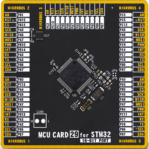
Type
8th Generation
Architecture
ARM Cortex-M4
MCU Memory (KB)
512
Silicon Vendor
STMicroelectronics
Pin count
64
RAM (Bytes)
262144
You complete me!
Accessories
The Type-K thermocouple, equipped with glass braid insulation, is a versatile tool designed for precision temperature measurements, particularly in high-temperature environments. With a calibrated Type-K configuration and a 24 AWG gage wire spanning 2 meters, this probe is engineered to provide reliable readings. Its operational temperature range extends to 480°C (900°F), making it suitable for demanding applications. The glass braid insulation ensures durability and stability during measurements, and the connector body can withstand temperatures up to 220°C (425°F). The Type-K thermocouple probe features a PCC-SMP connector at its end, which offers compatibility with THERMO Click and Thermo K Click boards. This connectivity makes it a valuable tool for various industrial and scientific settings, where precision and reliability in temperature monitoring are essential.

Used MCU Pins
mikroBUS™ mapper
Take a closer look
Click board™ Schematic
Step by step
Project assembly

Start by selecting your development board and Click board™. Begin with the Fusion for ARM v8 as your development board.


Track your results in real time
Application Output
1. Application Output - In Debug mode, the 'Application Output' window enables real-time data monitoring, offering direct insight into execution results. Ensure proper data display by configuring the environment correctly using the provided tutorial.

2. UART Terminal - Use the UART Terminal to monitor data transmission via a USB to UART converter, allowing direct communication between the Click board™ and your development system. Configure the baud rate and other serial settings according to your project's requirements to ensure proper functionality. For step-by-step setup instructions, refer to the provided tutorial.

3. Plot Output - The Plot feature offers a powerful way to visualize real-time sensor data, enabling trend analysis, debugging, and comparison of multiple data points. To set it up correctly, follow the provided tutorial, which includes a step-by-step example of using the Plot feature to display Click board™ readings. To use the Plot feature in your code, use the function: plot(*insert_graph_name*, variable_name);. This is a general format, and it is up to the user to replace 'insert_graph_name' with the actual graph name and 'variable_name' with the parameter to be displayed.

Software Support
Library Description
This library contains API for Thermo K Click driver.
Key functions:
thermok_get_temperature- Temperature datathermok_get_status- Get statusthermok_get_device_info- Functions for read device info
Open Source
Code example
The complete application code and a ready-to-use project are available through the NECTO Studio Package Manager for direct installation in the NECTO Studio. The application code can also be found on the MIKROE GitHub account.
/*!
 * \file
 * \brief ThermoK Click example
 *
 * # Description
 * Demo application shows basic temperature reading using Thermo K Click.
 *
 * The demo application is composed of two sections :
 *
 * ## Application Init
 * Configuring Clicks and log objects.
 * Reads the device ID and also checks the Click and MCU communication.
 *
 * ## Application Task
 * Reads Temperature data(Type K probe) and this data logs to USBUART every 500ms.
 *
 * \author Katarina Perendic
 *
 */
// ------------------------------------------------------------------- INCLUDES

#include "board.h"
#include "log.h"
#include "thermok.h"

// ------------------------------------------------------------------ VARIABLES

static thermok_t thermok;
static log_t logger;

static uint16_t device_info;

// ------------------------------------------------------ APPLICATION FUNCTIONS

void application_init ( void )
{
    log_cfg_t log_cfg;
    thermok_cfg_t cfg;

    /**
     * Logger initialization.
     * Default baud rate: 115200
     * Default log level: LOG_LEVEL_DEBUG
     * @note If USB_UART_RX and USB_UART_TX
     * are defined as HAL_PIN_NC, you will
     * need to define them manually for log to work.
     * See @b LOG_MAP_USB_UART macro definition for detailed explanation.
     */
    LOG_MAP_USB_UART( log_cfg );
    log_init( &logger, &log_cfg );
    log_info( &logger, "---- Application Init ----" );

    //  Click initialization.

    thermok_cfg_setup( &cfg );
    THERMOK_MAP_MIKROBUS( cfg, MIKROBUS_1 );
    thermok_init( &thermok, &cfg );

    // Check communication and reads device ID

    device_info = thermok_get_device_info( &thermok );

    if ( ( device_info >> 8 ) == THERMOK_DEVICE_ID )
    {
        log_info(&logger, "---- Communication OK!!! ----" );
    }
    else
    {
        log_info(&logger, "---- Communication ERROR!!! ----" );
        for ( ; ; );
    }
    Delay_1sec( );
}

void application_task ( void )
{
    float temperature;

    //  Task implementation.

    temperature = thermok_get_temperature( &thermok,
                                           THERMOK_REG_HOT_JUNCTION_TEMP_THR,
                                           THERMOK_TEMP_IN_CELSIUS );
    log_printf( &logger, ">> Temperature is %.2f C\r\n", temperature );

    Delay_ms ( 1000 );
    Delay_ms ( 500 );
}

int main ( void )
{
    /* Do not remove this line or clock might not be set correctly. */
    #ifdef PREINIT_SUPPORTED
    preinit();
    #endif

    application_init( );

    for ( ; ; )
    {
        application_task( );
    }

    return 0;
}


// ------------------------------------------------------------------------ END
Additional Support
Resources
Category:Temperature & humidity


