Achieve fan speed wizardry with MIC74 and TM4C1294NCPDT
Masters of the air

Published Jul 26, 2023
Click board™
Fan 3 click
Dev. board
Fusion for Tiva v8
Compiler
NECTO Studio
MCU
TM4C1294NCPDT
Where innovation meets optimal cooling performance
A
A
Hardware Overview
How does it work?
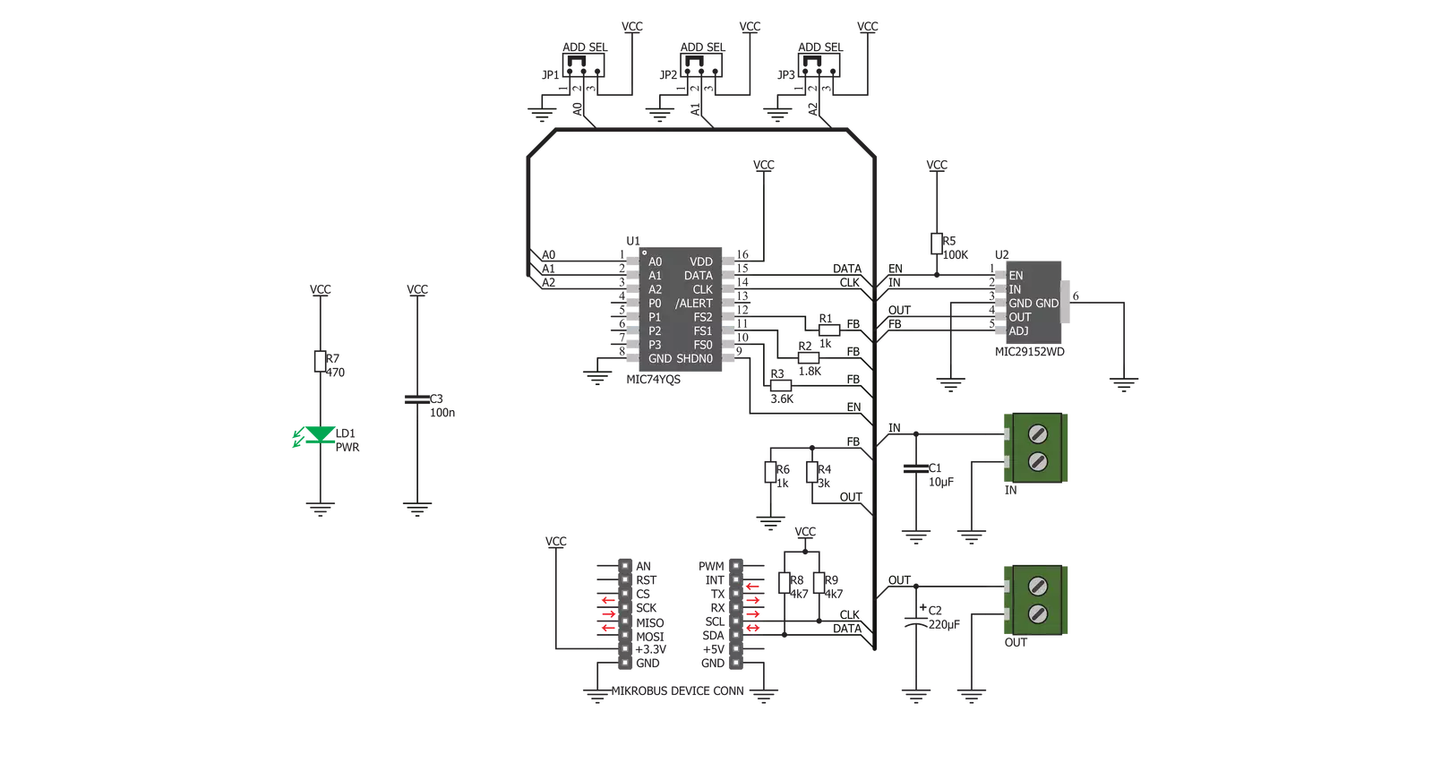
Fan 3 Click is based on the MIC74, a serial to parallel I/O expander and fan controller, and the MIC29152, a high current, high accuracy, low dropout voltage regulator both from Microchip. The four most significant bit outputs can be used to implement the fan speed control. This device uses an I2C communication protocol to set up dedicated internal registers. The CLK and DATA pins are routed to mikroBUS™ I2C pins. Also, those pins are already pulled up with the 4k7 resistors on the click board, so there is no need to use additional pull-up resistors. The three most significant bit outputs are equipped with resistors connected to the feedback input (ADJ) of the MIC29152. This regulator is used to output the regulated voltage for the fan, determined by the
feedback voltage on the ADJ pin. The regulator's output is set to 12V when the maximum speed is selected. The recommended input voltage should be at most 12V because, in that case, the regulating efficiency won't be optimal, and the excess power will be dissipated as the heat. The voltage regulator features an internal power limiting logic, which protects it from damage in case of an excessive load on its output. Individual open-drain output bits of the MIC74 are selectively grounded or allowed to float under the control of the internal state machine, so the equivalent resistance seen by the MIC29152 regulator's feedback path is raised or lowered, changing the output voltage that way. The fourth bit is set to work as the SHDN, which enables the voltage
regulator via its EN pin when the I2C selects the fan mode. Setting this bit will activate the voltage regulator, and the fan will start turning with the speed defined by the MIC74 registers. Fan 3 click can be used on several different I2C addresses, selectable by the ADD SEL jumpers. Those jumpers are used to directly set A0 to A2 address select pins of the MIC74. All address pins are grounded by default, which sets the slave I2C address to 0x20h. The click is equipped with two connectors. One connector connects an external voltage source fed to the regulator's input. The other connector is used to connect the load - usually an electromotor which works with the nominal voltage of 12V and has the fan blades attached to its rotor.

Features overview
Development board
Fusion for TIVA v8 is a development board specially designed for the needs of rapid development of embedded applications. It supports a wide range of microcontrollers, such as different 32-bit ARM® Cortex®-M based MCUs from Texas Instruments, regardless of their number of pins, and a broad set of unique functions, such as the first-ever embedded debugger/programmer over a WiFi network. The development board is well organized and designed so that the end-user has all the necessary elements, such as switches, buttons, indicators, connectors, and others, in one place. Thanks to innovative manufacturing technology, Fusion for TIVA v8 provides a fluid and immersive working experience, allowing access
anywhere and under any circumstances at any time. Each part of the Fusion for TIVA v8 development board contains the components necessary for the most efficient operation of the same board. An advanced integrated CODEGRIP programmer/debugger module offers many valuable programming/debugging options, including support for JTAG, SWD, and SWO Trace (Single Wire Output)), and seamless integration with the Mikroe software environment. Besides, it also includes a clean and regulated power supply module for the development board. It can use a wide range of external power sources, including a battery, an external 12V power supply, and a power source via the USB Type-C (USB-C) connector.
Communication options such as USB-UART, USB HOST/DEVICE, CAN (on the MCU card, if supported), and Ethernet is also included. In addition, it also has the well-established mikroBUS™ standard, a standardized socket for the MCU card (SiBRAIN standard), and two display options for the TFT board line of products and character-based LCD. Fusion for TIVA v8 is an integral part of the Mikroe ecosystem for rapid development. Natively supported by Mikroe software tools, it covers many aspects of prototyping and development thanks to a considerable number of different Click boards™ (over a thousand boards), the number of which is growing every day.

Microcontroller Overview
MCU Card / MCU
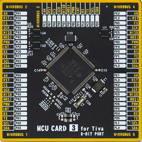
Type
8th Generation
Architecture
ARM Cortex-M4
MCU Memory (KB)
1024
Silicon Vendor
Texas Instruments
Pin count
128
RAM (Bytes)
262144
Used MCU Pins
mikroBUS™ mapper
Take a closer look
Click board™ Schematic
Step by step
Project assembly

Start by selecting your development board and Click board™. Begin with the Fusion for Tiva v8 as your development board.


Software Support
Library Description
This library contains API for Fan 3 Click driver.
Key functions:
fan3_set_speed- Set fan speed function
Open Source
Code example
The complete application code and a ready-to-use project are available through the NECTO Studio Package Manager for direct installation in the NECTO Studio. The application code can also be found on the MIKROE GitHub account.
/*!
 * \file
 * \brief Fan3 Click example
 *
 * # Description
 * This application controls the fan speed.
 *
 * The demo application is composed of two sections :
 *
 * ## Application Init
 * Initializes the Click device.
 *
 * ## Application Task
 * Cycles through different fan speeds, including 0 - stopped.
 *
 * \author MikroE Team
 *
 */
// ------------------------------------------------------------------- INCLUDES

#include "board.h"
#include "log.h"
#include "fan3.h"

// ------------------------------------------------------------------ VARIABLES

static fan3_t fan3;
static log_t logger;

// ------------------------------------------------------ APPLICATION FUNCTIONS

void application_init ( void )
{
    log_cfg_t log_cfg;
    fan3_cfg_t cfg;

    /**
     * Logger initialization.
     * Default baud rate: 115200
     * Default log level: LOG_LEVEL_DEBUG
     * @note If USB_UART_RX and USB_UART_TX
     * are defined as HAL_PIN_NC, you will
     * need to define them manually for log to work.
     * See @b LOG_MAP_USB_UART macro definition for detailed explanation.
     */
    LOG_MAP_USB_UART( log_cfg );
    log_init( &logger, &log_cfg );
    log_info( &logger, "---- Application Init ----" );

    //  Click initialization.

    fan3_cfg_setup( &cfg );
    FAN3_MAP_MIKROBUS( cfg, MIKROBUS_1 );
    fan3_init( &fan3, &cfg );

    log_printf( &logger, ">>> Initialized...\r\n" );
}

void application_task ( )
{
    log_printf( &logger, "Speed 1...\r\n" );
    fan3_set_speed( &fan3, FAN3_SPEED1 );
    Delay_ms ( 1000 );
    Delay_ms ( 1000 );
    Delay_ms ( 1000 );
    Delay_ms ( 1000 );
    log_printf( &logger, "Speed 3...\r\n" );
    fan3_set_speed( &fan3, FAN3_SPEED3 );
    Delay_ms ( 1000 );
    Delay_ms ( 1000 );
    Delay_ms ( 1000 );
    Delay_ms ( 1000 );
    log_printf( &logger, "Speed 5...\r\n" );
    fan3_set_speed( &fan3, FAN3_SPEED5 );
    Delay_ms ( 1000 );
    Delay_ms ( 1000 );
    Delay_ms ( 1000 );
    Delay_ms ( 1000 );
    log_printf( &logger, "Speed 7...\r\n" );
    fan3_set_speed( &fan3, FAN3_SPEED7 );
    Delay_ms ( 1000 );
    Delay_ms ( 1000 );
    Delay_ms ( 1000 );
    Delay_ms ( 1000 );
    log_printf( &logger, "Stopped...\r\n" );
    fan3_set_speed( &fan3, FAN3_STOPPED );
    Delay_ms ( 1000 );
    Delay_ms ( 1000 );
    Delay_ms ( 1000 );
    Delay_ms ( 1000 );
}

int main ( void )
{
    /* Do not remove this line or clock might not be set correctly. */
    #ifdef PREINIT_SUPPORTED
    preinit();
    #endif

    application_init( );

    for ( ; ; )
    {
        application_task( );
    }

    return 0;
}

// ------------------------------------------------------------------------ END


