Transmit data over the 315MHz frequency band with MICRF112 and MCU CARD for Tiva TM4C129ENCZAD
Powerful RF transmission for remote control, security, and keyless entry systems
Published Apr 22, 2024
Click board™
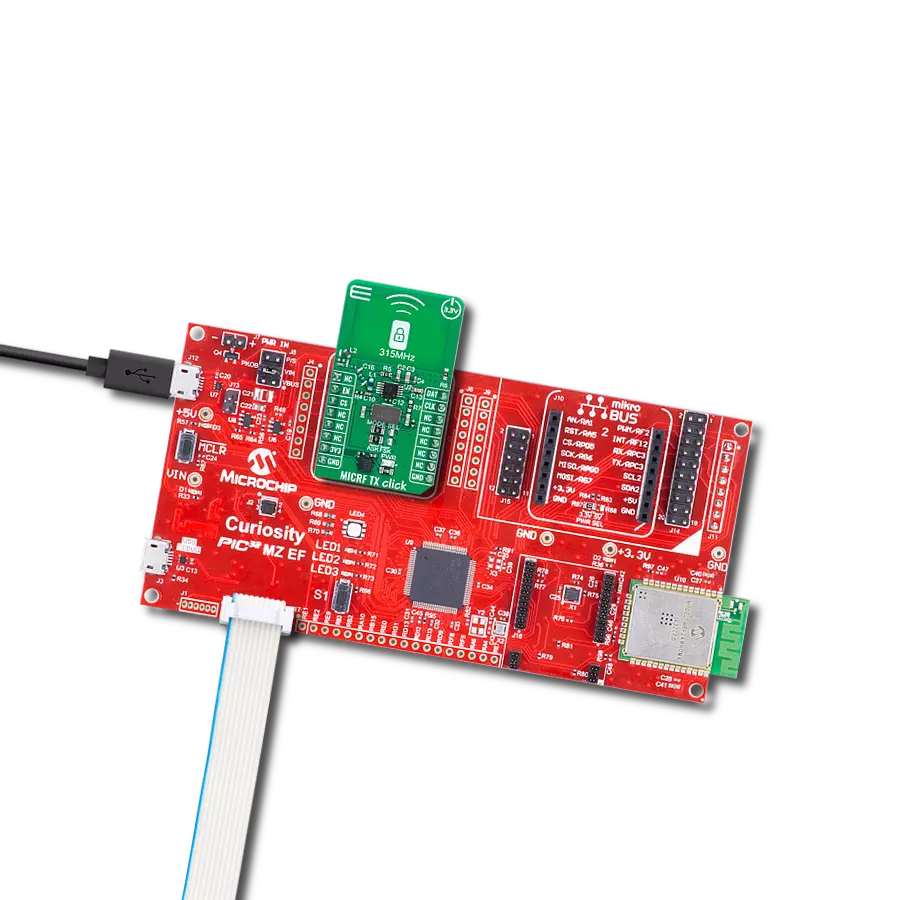
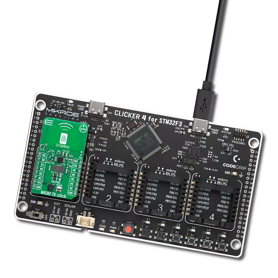
MICRF TX Click
Dev. board
Fusion for Tiva v8
Compiler
NECTO Studio
MCU
TM4C129ENCZAD
Perfect for automotive and building access control systems where reliable and sensitive signal reception is crucial.
A
A
Hardware Overview
How does it work?
MICRF TX Click is based on the MICRF112, an RF transmitter IC from Microchip. This high-performance IC is designed for simplicity in operation, functioning on a "Data-In, RF-Out" basis. It supports both Amplitude Shift Keying (ASK) and Frequency Shift Keying (FSK) modulation types and incorporates a Phase-Locked Loop (PLL) for reliable frequency stabilization. Specifically made for the 315MHz band, the MICRF112 requires only a basic crystal oscillator - such as the onboard 9.84375MHz crystal - to accurately establish its operating frequency alongside minimal external components to match the power amplifier's output with the antenna. It is ideally used in various applications like Remote Keyless Entry (RKE) systems, various remote controls (for set-top boxes, HVAC systems, and appliances), Garage
Door Openers (GDO), Tire Pressure Monitoring Systems (TPMS), outdoor weather stations, and systems for security, alarm, lighting and fan control, doorbells, irrigation, and more. Concerning the board's connectivity with an MCU, this board uses several pins on the mikroBUS™ socket. The EN pin functions as a chip enable function for toggling the device ON or OFF state. The DAT pin directly accepts modulation data input (ASK or FSK, determined by the MODE SEL jumper's setting). In the case of FSK modulation, an additional capacitor like C12 is required between the XTLOUT and XTAL_MOD pins of the MICRF112 (C12 not populated by default). If the user desires a different frequency than the onboard oscillator, they should desolder the R7 resistor on the board, thereby disconnecting the onboard oscillator. Then, a 1nF
capacitor should be soldered in place of the C13 capacitor, and the CLK pin is then used as the reference oscillator input. Operating with a 3.3V input from the mikroBUS™ power supply, the MICRF112 can generate a continuous wave (CW) output power of +10dBm into a 50Ω antenna load. It also boasts an energy-efficient shutdown mode, drawing a mere 50nA, making it highly suitable for battery-dependent devices. This Click board™ can be operated only with a 3.3V logic voltage level. The board must perform appropriate logic voltage level conversion before using MCUs with different logic levels. Also, it comes equipped with a library containing functions and an example code that can be used as a reference for further development.

Features overview
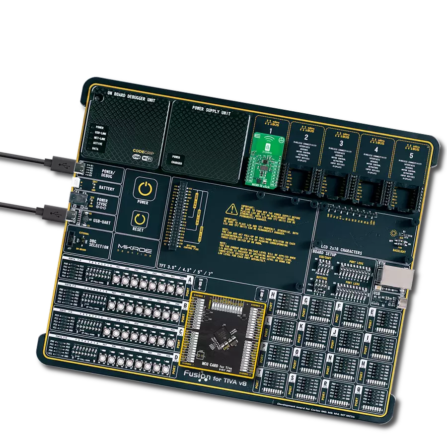
Development board
Fusion for TIVA v8 is a development board specially designed for the needs of rapid development of embedded applications. It supports a wide range of microcontrollers, such as different 32-bit ARM® Cortex®-M based MCUs from Texas Instruments, regardless of their number of pins, and a broad set of unique functions, such as the first-ever embedded debugger/programmer over a WiFi network. The development board is well organized and designed so that the end-user has all the necessary elements, such as switches, buttons, indicators, connectors, and others, in one place. Thanks to innovative manufacturing technology, Fusion for TIVA v8 provides a fluid and immersive working experience, allowing access
anywhere and under any circumstances at any time. Each part of the Fusion for TIVA v8 development board contains the components necessary for the most efficient operation of the same board. An advanced integrated CODEGRIP programmer/debugger module offers many valuable programming/debugging options, including support for JTAG, SWD, and SWO Trace (Single Wire Output)), and seamless integration with the Mikroe software environment. Besides, it also includes a clean and regulated power supply module for the development board. It can use a wide range of external power sources, including a battery, an external 12V power supply, and a power source via the USB Type-C (USB-C) connector.
Communication options such as USB-UART, USB HOST/DEVICE, CAN (on the MCU card, if supported), and Ethernet is also included. In addition, it also has the well-established mikroBUS™ standard, a standardized socket for the MCU card (SiBRAIN standard), and two display options for the TFT board line of products and character-based LCD. Fusion for TIVA v8 is an integral part of the Mikroe ecosystem for rapid development. Natively supported by Mikroe software tools, it covers many aspects of prototyping and development thanks to a considerable number of different Click boards™ (over a thousand boards), the number of which is growing every day.

Microcontroller Overview
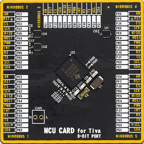
MCU Card / MCU
Type
8th Generation
Architecture
ARM Cortex-M4
MCU Memory (KB)
1024
Silicon Vendor
Texas Instruments
Pin count
212
RAM (Bytes)
262144
Used MCU Pins
mikroBUS™ mapper
Take a closer look
Click board™ Schematic

Step by step
Project assembly

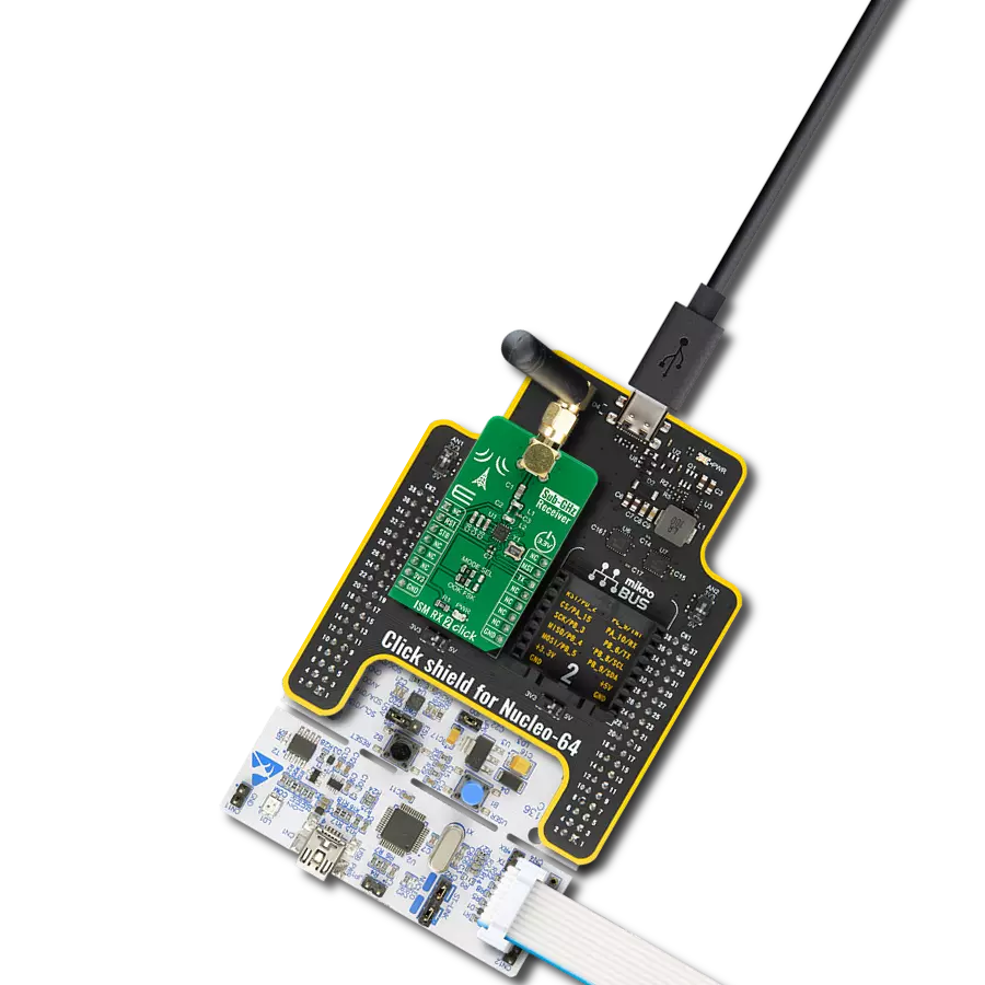
Start by selecting your development board and Click board™. Begin with the Fusion for Tiva v8 as your development board.


Track your results in real time
Application Output
1. Application Output - In Debug mode, the 'Application Output' window enables real-time data monitoring, offering direct insight into execution results. Ensure proper data display by configuring the environment correctly using the provided tutorial.

2. UART Terminal - Use the UART Terminal to monitor data transmission via a USB to UART converter, allowing direct communication between the Click board™ and your development system. Configure the baud rate and other serial settings according to your project's requirements to ensure proper functionality. For step-by-step setup instructions, refer to the provided tutorial.

3. Plot Output - The Plot feature offers a powerful way to visualize real-time sensor data, enabling trend analysis, debugging, and comparison of multiple data points. To set it up correctly, follow the provided tutorial, which includes a step-by-step example of using the Plot feature to display Click board™ readings. To use the Plot feature in your code, use the function: plot(*insert_graph_name*, variable_name);. This is a general format, and it is up to the user to replace 'insert_graph_name' with the actual graph name and 'variable_name' with the parameter to be displayed.

Software Support
Library Description
This library contains API for MICRF TX Click driver.
Key functions:
micrftx_send_data- This function builds and sends a packet of data. The packet format is as follows (MSB first, manchester IEEE 802.3): MICRFTX_TRAINING_BYTES, PREABMLE, LEN, DATA_IN, CRC16 (calculated from whole packet excluding training bytes).
Open Source
Code example
The complete application code and a ready-to-use project are available through the NECTO Studio Package Manager for direct installation in the NECTO Studio. The application code can also be found on the MIKROE GitHub account.
/*!
 * @file main.c
 * @brief MICRF TX Click Example.
 *
 * # Description
 * This example demonstrates the use of MICRF TX Click board by sending
 * a predefined message to the receiver.
 *
 * The demo application is composed of two sections :
 *
 * ## Application Init
 * Initializes the driver and logger.
 *
 * ## Application Task
 * Sends a predefined message every 3 seconds and displays it on the USB UART.
 *
 * @note
 * The MICRF RX Click board is a compatible receiver for the MICRF TX Click.
 * Here are a few steps for troubleshooting if you are experiencing issues running
 * this example:
 *  - Make sure the MICRF TX Click is set to ASK mode with on-board jumpers.
 *  - Check the MCU clock configuration, use an external oscillator instead of the MCU's
 * internal one for better accuracy on manchester data rate delay.
 *  - Measure the actual data rate on the data line and adjust the MICRFTX_MAN_BIT_LEN_US
 * value accordingly.
 *
 * @author Stefan Filipovic
 *
 */

#include "board.h"
#include "log.h"
#include "micrftx.h"

#define MICRFTX_PREAMBLE        0x5AA5      /**< Packet preamble word. */
#define MICRFTX_MESSAGE         "MIKROE"    /**< Text message to send. */

static micrftx_t micrftx;       /**< MICRF TX Click driver object. */
static log_t logger;            /**< Logger object. */

/**
 * @brief MICRF TX send data function.
 * @details This function builds and sends a packet of data.
 * The packet format is as follows (MSB first, manchester IEEE 802.3):
 * MICRFTX_TRAINING_BYTES, PREABMLE, LEN, DATA_IN, CRC16 (calculated from whole packet excluding training bytes).
 * @param[in] ctx : Click context object.
 * See #micrftx_t object definition for detailed explanation.
 * @param[in] preamble : Preamble word.
 * @param[in] data_in : Data buffer.
 * @param[in] len : Number of bytes in data buffer.
 * @return None.
 * @note Default manchester bit length is set to 2000us.
 */
static void micrftx_send_data ( micrftx_t *ctx, uint16_t preamble, uint8_t *data_in, uint8_t len );

/**
 * @brief Manchester encode bits.
 * @details This function encodes a data byte to manchester word (IEEE 802.3).
 * @return Manchester word.
 * @note None.
 */
static uint16_t micrftx_man_encode ( uint8_t data_in );

/**
 * @brief Reflect bits.
 * @details This function reflects a desired number of bits in data.
 * @return Reflected data.
 * @note None.
 */
static uint16_t micrftx_reflect_bits( uint16_t data_in, uint8_t len );

/**
 * @brief CRC-16/MAXIM calculation for CRC16 function.
 * @details This function calculates CRC16 with parameteres:
 * @li @c  Width 16 bit
 * @li @c  Polynomial 0x8005 ( x16 + x15 + x2 + x0 )
 * @li @c  Initialization 0x0000
 * @li @c  Reflect input True
 * @li @c  Reflect output True
 * @li @c  Final Xor 0xFFFF
 * @li @c  Example { 69, 00 } - 0xAFD1
 * @param[in] data_buf : Array of bytes to calculate crc from.
 * @param[in] len : Number of bytes to calculate crc from.
 * @return Calculated CRC.
 * @note None.
 */
static uint16_t micrftx_calculate_crc16 ( uint8_t *data_buf, uint16_t len );

void application_init ( void )
{
    log_cfg_t log_cfg;          /**< Logger config object. */
    micrftx_cfg_t micrftx_cfg;  /**< Click config object. */

    /**
     * Logger initialization.
     * Default baud rate: 115200
     * Default log level: LOG_LEVEL_DEBUG
     * @note If USB_UART_RX and USB_UART_TX
     * are defined as HAL_PIN_NC, you will
     * need to define them manually for log to work.
     * See @b LOG_MAP_USB_UART macro definition for detailed explanation.
     */
    LOG_MAP_USB_UART( log_cfg );
    log_init( &logger, &log_cfg );
    log_info( &logger, " Application Init " );

    // Click initialization.
    micrftx_cfg_setup( &micrftx_cfg );
    MICRFTX_MAP_MIKROBUS( micrftx_cfg, MIKROBUS_1 );
    if ( DIGITAL_OUT_UNSUPPORTED_PIN == micrftx_init( &micrftx, &micrftx_cfg ) )
    {
        log_error( &logger, " Communication init." );
        for ( ; ; );
    }

    log_info( &logger, " Application Task " );
}

void application_task ( void )
{
    log_printf ( &logger, " Sending data: %s\r\n\n", ( char * ) MICRFTX_MESSAGE );
    micrftx_send_data ( &micrftx, MICRFTX_PREAMBLE, MICRFTX_MESSAGE, strlen ( MICRFTX_MESSAGE ) );
    Delay_ms ( 1000 );
    Delay_ms ( 1000 );
    Delay_ms ( 1000 );
}

int main ( void )
{
    /* Do not remove this line or clock might not be set correctly. */
    #ifdef PREINIT_SUPPORTED
    preinit();
    #endif

    application_init( );

    for ( ; ; )
    {
        application_task( );
    }

    return 0;
}

static void micrftx_send_data ( micrftx_t *ctx, uint16_t preamble, uint8_t *data_in, uint8_t len )
{
    uint8_t training[ ] = MICRFTX_TRAINING_BYTES;
    uint8_t packet_buf[ MICRFTX_MAX_DATA_LEN + 5 ] = { 0 };
    uint16_t crc = 0;
    uint16_t man_data = 0;
    uint8_t byte_cnt = 0;
    uint8_t bit_cnt = 0;

    packet_buf[ 0 ] = ( uint8_t ) ( ( preamble >> 8 ) & 0xFF );
    packet_buf[ 1 ] = ( uint8_t ) ( preamble & 0xFF );
    packet_buf[ 2 ] = len;
    memcpy ( &packet_buf[ 3 ], data_in, len );
    crc = micrftx_calculate_crc16 ( packet_buf, len + 3 );
    packet_buf[ len + 3 ] = ( uint8_t ) ( ( crc >> 8 ) & 0xFF );
    packet_buf[ len + 4 ] = ( uint8_t ) ( crc & 0xFF );

    micrftx_enable_device ( ctx );
    Delay_10ms( );
    // Send training bytes first
    for ( byte_cnt = 0; byte_cnt < sizeof ( training ); byte_cnt++ )
    {
        man_data = micrftx_man_encode ( training[ byte_cnt ] );
        for ( bit_cnt = 0; bit_cnt < 16; bit_cnt++ )
        {
            if ( man_data & MICRFTX_MAN_MSB )
            {
                micrftx_set_data_pin ( ctx );
            }
            else
            {
                micrftx_clear_data_pin ( ctx );
            }
            man_data <<= 1;
            Delay_us ( MICRFTX_MAN_BIT_LEN_US / 2 );
        }
    }
    // Send the packet bytes
    for ( byte_cnt = 0; byte_cnt < ( len + 5 ); byte_cnt++ )
    {
        man_data = micrftx_man_encode ( packet_buf[ byte_cnt ] );
        for ( bit_cnt = 0; bit_cnt < 16; bit_cnt++ )
        {
            if ( man_data & MICRFTX_MAN_MSB )
            {
                micrftx_set_data_pin ( ctx );
            }
            else
            {
                micrftx_clear_data_pin ( ctx );
            }
            man_data <<= 1;
            Delay_us ( MICRFTX_MAN_BIT_LEN_US / 2 );
        }
    }
    Delay_10ms( );
    micrftx_disable_device ( ctx );
}

static uint16_t micrftx_man_encode ( uint8_t data_in )
{
    uint16_t man_data = 0;

    for ( uint8_t bit_cnt = 0; bit_cnt < 8; bit_cnt++ )
    {
        man_data <<= 2;
        if ( data_in & ( 0x80 >> bit_cnt ) )
        {
            man_data |= 1;  // 1: low going to a high
        }
        else
        {
            man_data |= 2;  // 0: high going to a low
        }
    }
    return man_data;
}

static uint16_t micrftx_reflect_bits( uint16_t data_in, uint8_t len )
{
    uint16_t data_out = 0;
    for ( uint16_t cnt = 0; cnt < len; cnt++ )
    {
        data_out |= ( ( data_in >> cnt ) & 1 ) << ( len - cnt - 1 );
    }
    return data_out;
}

static uint16_t micrftx_calculate_crc16( uint8_t *data_buf, uint16_t len )
{
    uint16_t crc16 = 0x0000;
    for ( uint16_t cnt = 0; cnt < len; cnt++ )
    {
        crc16 ^= ( micrftx_reflect_bits( data_buf[ cnt ], 8 ) << 8 );
        for ( uint8_t bit_cnt = 0; bit_cnt < 8; bit_cnt++ )
        {
            if ( crc16 & 0x8000 )
            {
                crc16 = ( crc16 << 1 ) ^ 0x8005;
            }
            else
            {
                crc16 <<= 1;
            }
        }
    }
    return micrftx_reflect_bits( crc16, 16 ) ^ 0xFFFF;
}

// ------------------------------------------------------------------------ END
Additional Support
Resources
Category:Sub-1 GHz Transceievers