Create a dependable pressure measurement solution with MS580314BA01-00 and STM32F302VC
Absolute pressure sensory unit

Published Jul 22, 2025
Click board™
Pressure 2 Click
Dev. board
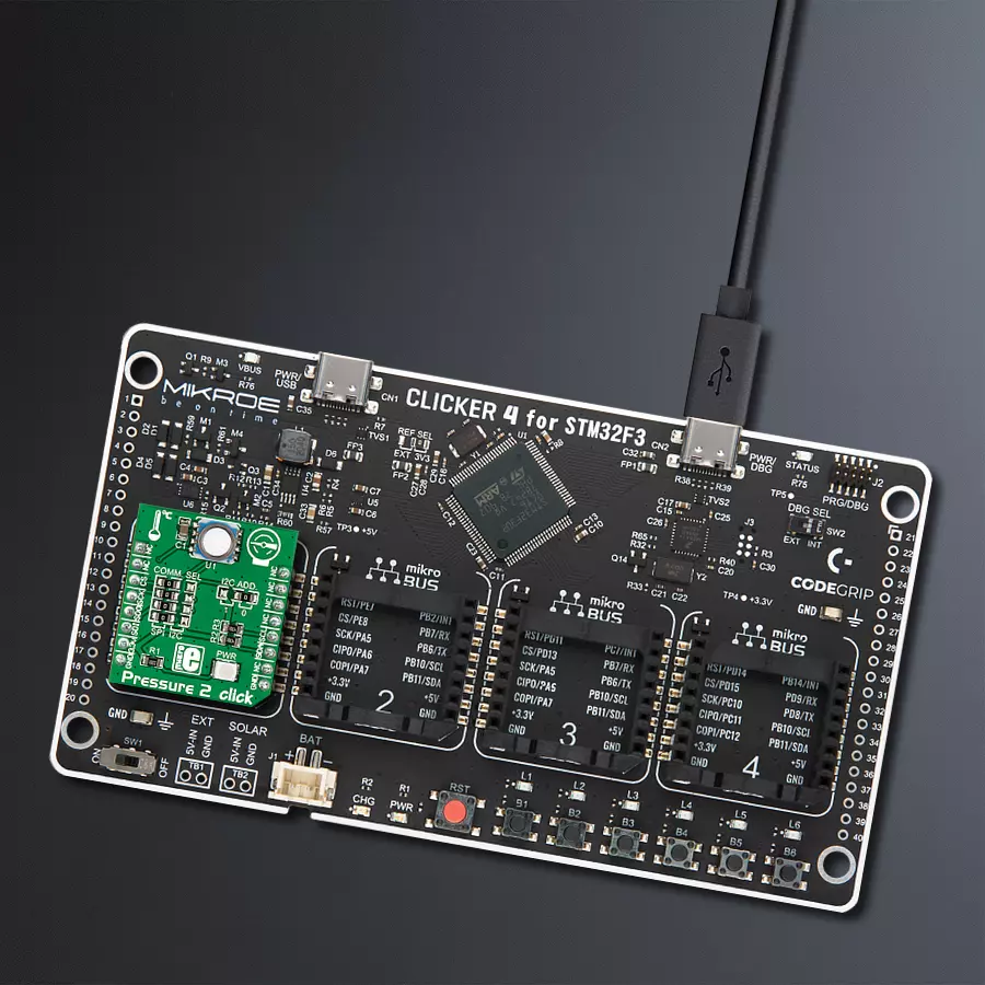
CLICKER 4 for STM32F302VCT6
Compiler
NECTO Studio
MCU
STM32F302VC
Harsh environment pressure sensing solution built to last!
A
A
Hardware Overview
How does it work?
Pressure 2 Click is based on the MS580314BA01-00, a high accuracy, low-power, and low noise 24-bit absolute pressure/altitude sensor from TE Connectivity Measurement Specialties. The MS580314BA01-00 combines an ultra-low power 24-bit ΔΣ ADC with internal factory-calibrated coefficients and a high linearity pressure sensor to optimize current consumption and conversion speed while providing different operation modes and a precise digital 24-bit pressure and temperature value. The MS580314BA01-00 is accurate, covering a wide measurement pressure range from 0 to 14.000mbar over a wide operating temperature range from -40 to +85°C, and its
accuracy from -200 to +100mbar (typical accuracy of 20mbar). The MS580314BA01-00 is based on leading MEMS technology and the latest benefits from TE Connectivity. This sensing principle leads to very low hysteresis and high pressure and temperature signal stability. Also, the gel protection and antimagnetic stainless steel cap make the MS580314BA01-00 durable up to 30bars of pressure. Pressure 2 Click allows using both I2C and SPI interfaces with a maximum frequency of 400kHz for I2C and 20MHz for SPI communication. The selection can be made by positioning SMD jumpers labeled as COMM SEL in an appropriate position. Note that all the jumpers' positions must
be on the same side, or the Click board™ may become unresponsive. While the I2C interface is selected, the MS580314BA01-00 allows choosing the least significant bit (LSB) of its I2C slave address using the SMD jumper labeled I2C ADD. This Click board™ can be operated only with a 3.3V logic voltage level. The board must perform appropriate logic voltage level conversion before using MCUs with different logic levels. However, the Click board™ comes equipped with a library containing functions and an example code that can be used as a reference for further development.

Features overview
Development board
Clicker 4 for STM32F3 is a compact development board designed as a complete solution, you can use it to quickly build your own gadgets with unique functionalities. Featuring a STM32F302VCT6, four mikroBUS™ sockets for Click boards™ connectivity, power managment, and more, it represents a perfect solution for the rapid development of many different types of applications. At its core, there is a STM32F302VCT6 MCU, a powerful microcontroller by STMicroelectronics, based on the high-
performance Arm® Cortex®-M4 32-bit processor core operating at up to 168 MHz frequency. It provides sufficient processing power for the most demanding tasks, allowing Clicker 4 to adapt to any specific application requirements. Besides two 1x20 pin headers, four improved mikroBUS™ sockets represent the most distinctive connectivity feature, allowing access to a huge base of Click boards™, growing on a daily basis. Each section of Clicker 4 is clearly marked, offering an intuitive and clean interface. This makes working with the development
board much simpler and thus, faster. The usability of Clicker 4 doesn’t end with its ability to accelerate the prototyping and application development stages: it is designed as a complete solution which can be implemented directly into any project, with no additional hardware modifications required. Four mounting holes [4.2mm/0.165”] at all four corners allow simple installation by using mounting screws. For most applications, a nice stylish casing is all that is needed to turn the Clicker 4 development board into a fully functional, custom design.

Microcontroller Overview
MCU Card / MCU

Architecture
ARM Cortex-M4
MCU Memory (KB)
256
Silicon Vendor
STMicroelectronics
Pin count
100
RAM (Bytes)
40960
Used MCU Pins
mikroBUS™ mapper
Take a closer look
Click board™ Schematic

Step by step
Project assembly

Start by selecting your development board and Click board™. Begin with the CLICKER 4 for STM32F302VCT6 as your development board.


Track your results in real time
Application Output
1. Application Output - In Debug mode, the 'Application Output' window enables real-time data monitoring, offering direct insight into execution results. Ensure proper data display by configuring the environment correctly using the provided tutorial.

2. UART Terminal - Use the UART Terminal to monitor data transmission via a USB to UART converter, allowing direct communication between the Click board™ and your development system. Configure the baud rate and other serial settings according to your project's requirements to ensure proper functionality. For step-by-step setup instructions, refer to the provided tutorial.

3. Plot Output - The Plot feature offers a powerful way to visualize real-time sensor data, enabling trend analysis, debugging, and comparison of multiple data points. To set it up correctly, follow the provided tutorial, which includes a step-by-step example of using the Plot feature to display Click board™ readings. To use the Plot feature in your code, use the function: plot(*insert_graph_name*, variable_name);. This is a general format, and it is up to the user to replace 'insert_graph_name' with the actual graph name and 'variable_name' with the parameter to be displayed.

Software Support
Library Description
This library contains API for Pressure 2 Click driver.
Key functions:
pressure2_read_coefficient- This function read calibration coefficients and return coefficientpressure2_send_cmd_adc- This function preforms ADC conversion and return 24-bit resultpressure2_read_sensor- Functions for readding sensor
Open Source
Code example
The complete application code and a ready-to-use project are available through the NECTO Studio Package Manager for direct installation in the NECTO Studio. The application code can also be found on the MIKROE GitHub account.
/*!
 * \file
 * \brief Pressure2 Click example
 *
 * # Description
 * This application measures pressure in range from 0 to 14 bars
 * (with a resolution of up to 0.2 mbars), but because of the stainless
 * steel cap enclosure, the sensor can withstand up to 30 bars of pressure.
 *
 * The demo application is composed of two sections :
 *
 * ## Application Init
 * Initializes driver init and chip init.
 *
 * ## Application Task
 * Reads sensor and logs to USB UART pressure and temperature every second.
 *
 * \author MikroE Team
 *
 */
// ------------------------------------------------------------------- INCLUDES

#include "board.h"
#include "log.h"
#include "pressure2.h"

// ------------------------------------------------------------------ VARIABLES

static pressure2_t pressure2;
static log_t logger;

static float pressure;
static float temperature;

// ------------------------------------------------------ APPLICATION FUNCTIONS

void application_init ( void )
{
    log_cfg_t log_cfg;
    pressure2_cfg_t pressure2_cfg;

    /**
     * Logger initialization.
     * Default baud rate: 115200
     * Default log level: LOG_LEVEL_DEBUG
     * @note If USB_UART_RX and USB_UART_TX
     * are defined as HAL_PIN_NC, you will
     * need to define them manually for log to work.
     * See @b LOG_MAP_USB_UART macro definition for detailed explanation.
     */
    LOG_MAP_USB_UART( log_cfg );
    log_init( &logger, &log_cfg );
    log_info( &logger, " Application Init " );

    // Click initialization.
    pressure2_cfg_setup( &pressure2_cfg );
    PRESSURE2_MAP_MIKROBUS( pressure2_cfg, MIKROBUS_1 );
    if ( SPI_MASTER_ERROR == pressure2_init( &pressure2, &pressure2_cfg ) )
    {
        log_error( &logger, " Communication init." );
        for ( ; ; );
    }

    if ( PRESSURE2_ERROR == pressure2_default_cfg ( &pressure2 ) )
    {
        log_error( &logger, " Default configuration." );
        for ( ; ; );
    }

    log_info( &logger, " Application Task " );
}

void application_task ( void )
{
    pressure2_read_sensor( &pressure2, &pressure, &temperature );

    log_printf( &logger," Pressure: %.2f mBar\r\n", pressure );
    log_printf( &logger," Temperature: %.2f degC\r\n\n", temperature );

    Delay_ms ( 1000 );
}

int main ( void )
{
    /* Do not remove this line or clock might not be set correctly. */
    #ifdef PREINIT_SUPPORTED
    preinit();
    #endif

    application_init( );

    for ( ; ; )
    {
        application_task( );
    }

    return 0;
}


// ------------------------------------------------------------------------ END
Additional Support
Resources
Category:Pressure


