Make informed choices by obtaining trustworthy weight data with PGA302 and TM4C129ENCPDT
Where every gram counts!
Published Aug 29, 2023
Click board™
Load Cell 3 Click
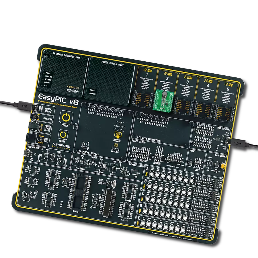
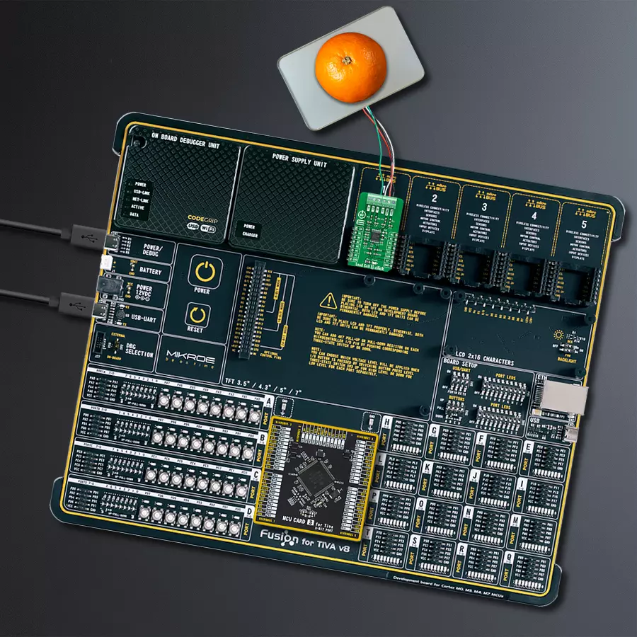
Dev. board
Fusion for Tiva v8
Compiler
NECTO Studio
MCU
TM4C129ENCPDT
Enable fair and reliable trade through dependable weight measurements.
A
A
Hardware Overview
How does it work?
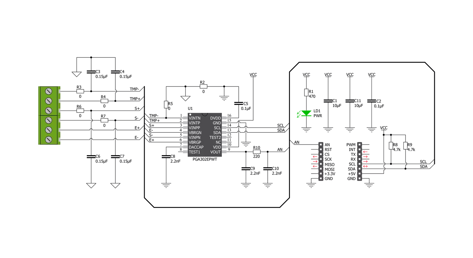
Load Cell 3 Click is based on the PGA302, a high accuracy, low drift, low noise, low power, and versatile signal conditioner automotive grade-qualified device for resistive bridge pressure and temperature-sensing applications from Texas Instruments. The PGA302 provides bridge excitation voltages of 2.5V. The PGA302 conditions sensing and temperature signals by amplifying and digitizing through the analog front-end chain and performing linearization and temperature compensation. The conditioned signals can be output in analog form, and besides that, the signal data can be accessed by an I2C digital interface. The PGA302 contains two separated analog-front
end (AFE) chains with their gain amplifiers for resistive bridge and temperature sensing inputs. The resistive bridge input AFE chain consists of a programmable gain with eight steps from 1.33V/V to 200V/V. For the temperature-sensing input AFE chain, the PGA302 provides a current source of up to 1mA for the optional external temperature sensing available on the onboard terminal labeled with TMP+ and TMP-. After the ADC decimation filters, the digitalized signals are sent to the linearization and compensation calculation digital signal logic. All required parameters for the linearization algorithm and other user data are stored in the integrated EEPROM memory.
At the device's output, a 14-bit DAC is followed by a ratiometric-voltage supply output buffer with a gain of 4 V/V, allowing a 0-5V ratiometric voltage system output available on the AN pin on the mikroBUS™ socket. This Click board™ can be operated only with a 5V logic voltage level. The board must perform appropriate logic voltage level conversion before using MCUs with different logic levels. Also, it comes equipped with a library containing functions and an example code that can be used as a reference for further development.


Features overview
Development board
Fusion for TIVA v8 is a development board specially designed for the needs of rapid development of embedded applications. It supports a wide range of microcontrollers, such as different 32-bit ARM® Cortex®-M based MCUs from Texas Instruments, regardless of their number of pins, and a broad set of unique functions, such as the first-ever embedded debugger/programmer over a WiFi network. The development board is well organized and designed so that the end-user has all the necessary elements, such as switches, buttons, indicators, connectors, and others, in one place. Thanks to innovative manufacturing technology, Fusion for TIVA v8 provides a fluid and immersive working experience, allowing access
anywhere and under any circumstances at any time. Each part of the Fusion for TIVA v8 development board contains the components necessary for the most efficient operation of the same board. An advanced integrated CODEGRIP programmer/debugger module offers many valuable programming/debugging options, including support for JTAG, SWD, and SWO Trace (Single Wire Output)), and seamless integration with the Mikroe software environment. Besides, it also includes a clean and regulated power supply module for the development board. It can use a wide range of external power sources, including a battery, an external 12V power supply, and a power source via the USB Type-C (USB-C) connector.
Communication options such as USB-UART, USB HOST/DEVICE, CAN (on the MCU card, if supported), and Ethernet is also included. In addition, it also has the well-established mikroBUS™ standard, a standardized socket for the MCU card (SiBRAIN standard), and two display options for the TFT board line of products and character-based LCD. Fusion for TIVA v8 is an integral part of the Mikroe ecosystem for rapid development. Natively supported by Mikroe software tools, it covers many aspects of prototyping and development thanks to a considerable number of different Click boards™ (over a thousand boards), the number of which is growing every day.

Microcontroller Overview
MCU Card / MCU

Type
8th Generation
Architecture
ARM Cortex-M4
MCU Memory (KB)
1024
Silicon Vendor
Texas Instruments
Pin count
128
RAM (Bytes)
262144
Used MCU Pins
mikroBUS™ mapper
Take a closer look
Click board™ Schematic
Step by step
Project assembly

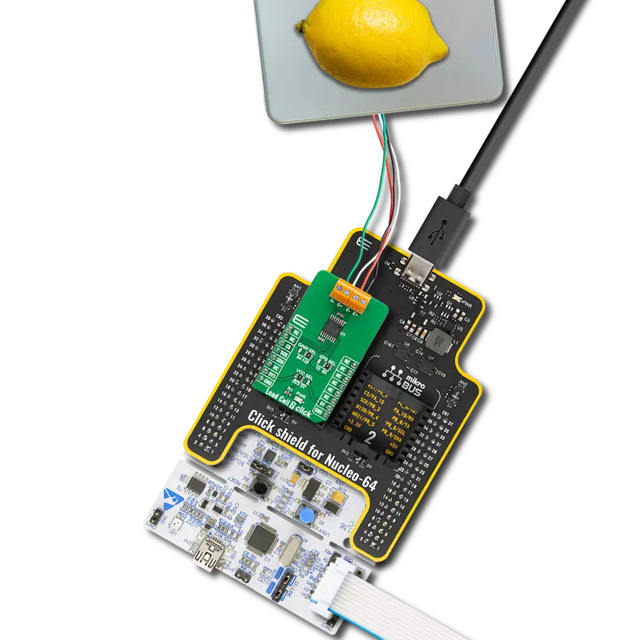
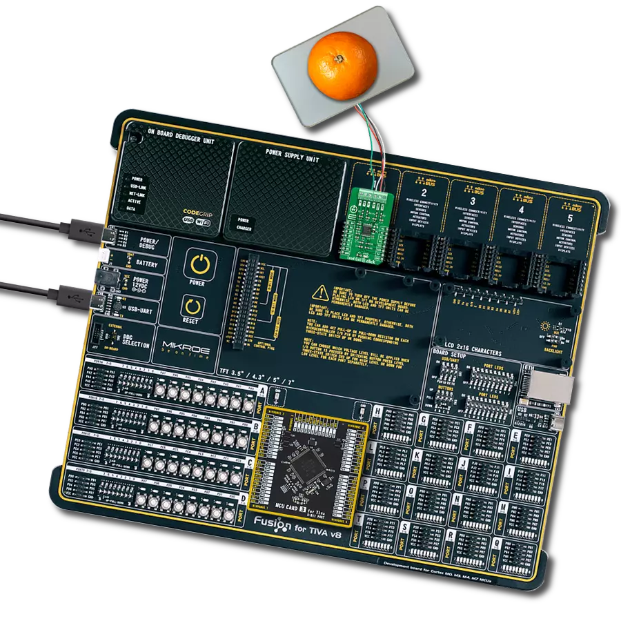
Start by selecting your development board and Click board™. Begin with the Fusion for Tiva v8 as your development board.


Software Support
Library Description
This library contains API for Load Cell 3 Click driver.
Key functions:
loadcell3_tare- Load Cell 3 tare the scales functionloadcell3_calibration- Load Cell 3 calibration functionloadcell3_get_weight- Load Cell 3 get weight function
Open Source
Code example
The complete application code and a ready-to-use project are available through the NECTO Studio Package Manager for direct installation in the NECTO Studio. The application code can also be found on the MIKROE GitHub account.
/*!
 * @file main.c
 * @brief LoadCell3 Click example
 *
 * # Description
 * This library contains API for the Load Cell 3 Click driver.
 * The library also includes a function for tare and calibration and weight measurement.
 * This demo application shows an example of weight measurement.
 *
 * The demo application is composed of two sections :
 *
 * ## Application Init
 * Initialization of I2C module and log UART.
 * After driver initialization and default settings, the app sets tare the scale,
 * calibrate scale and start measurements.
 *
 * ## Application Task
 * This is an example that shows the use of a Load Cell 3 Click board™.
 * The Load Cell 3 Click board can be used to measure weight,
 * shows the measurement of scales in grams [ g ].
 * Results are being sent to the Usart Terminal where you can track their changes.
 *
 * @author Nenad Filipovic
 *
 */

#include "board.h"
#include "log.h"
#include "loadcell3.h"

static loadcell3_t loadcell3;
static log_t logger;

static loadcell3_data_t cell_data;
static float weight_val;

void application_init ( void ) {
    log_cfg_t log_cfg;              /**< Logger config object. */
    loadcell3_cfg_t loadcell3_cfg;  /**< Click config object. */

    /**
     * Logger initialization.
     * Default baud rate: 115200
     * Default log level: LOG_LEVEL_DEBUG
     * @note If USB_UART_RX and USB_UART_TX
     * are defined as HAL_PIN_NC, you will
     * need to define them manually for log to work.
     * See @b LOG_MAP_USB_UART macro definition for detailed explanation.
     */
    LOG_MAP_USB_UART( log_cfg );
    log_init( &logger, &log_cfg );
    log_info( &logger, " Application Init " );

    // Click initialization.

    loadcell3_cfg_setup( &loadcell3_cfg );
    LOADCELL3_MAP_MIKROBUS( loadcell3_cfg, MIKROBUS_1 );
    err_t init_flag = loadcell3_init( &loadcell3, &loadcell3_cfg );
    if ( init_flag == I2C_MASTER_ERROR ) {
        log_error( &logger, " Application Init Error. " );
        log_info( &logger, " Please, run program again... " );

        for ( ; ; );
    }

    loadcell3_default_cfg ( &loadcell3 );
    log_info( &logger, " Application Task " );
    Delay_ms ( 100 );

    log_printf( &logger, "-------------------------\r\n" );
    log_printf( &logger, "     Tare the scale :    \r\n" );
    log_printf( &logger, "- - - - - - - - - - - - -\r\n" );
    log_printf( &logger, " >> Remove all object << \r\n" );
    log_printf( &logger, "- - - - - - - - - - - - -\r\n" );
    log_printf( &logger, " In the following 10 sec \r\n" );
    log_printf( &logger, " please remove all object\r\n" );
    log_printf( &logger, "     from the scale.     \r\n" );
    // 10 seconds delay
    Delay_ms ( 1000 );
    Delay_ms ( 1000 );
    Delay_ms ( 1000 );
    Delay_ms ( 1000 );
    Delay_ms ( 1000 );
    Delay_ms ( 1000 );
    Delay_ms ( 1000 );
    Delay_ms ( 1000 );
    Delay_ms ( 1000 );
    Delay_ms ( 1000 );

    log_printf( &logger, "-------------------------\r\n" );
    log_printf( &logger, "    Start tare scales    \r\n" );
    loadcell3_tare ( &loadcell3, &cell_data );
    Delay_ms ( 500 );

    log_printf( &logger, "-------------------------\r\n" );
    log_printf( &logger, "   Tarring is complete   \r\n" );
    log_printf( &logger, "-------------------------\r\n" );
    log_printf( &logger, "    Calibrate Scale :    \r\n" );
    log_printf( &logger, "- - - - - - - - - - - - -\r\n" );
    log_printf( &logger, "   >>> Load etalon <<<   \r\n" );
    log_printf( &logger, "- - - - - - - - - - - - -\r\n" );
    log_printf( &logger, " In the following 10 sec \r\n" );
    log_printf( &logger, "place 100g weight etalon \r\n" );
    log_printf( &logger, "    on the scale for     \r\n" );
    log_printf( &logger, "   calibration purpose.  \r\n" );
    // 10 seconds delay
    Delay_ms ( 1000 );
    Delay_ms ( 1000 );
    Delay_ms ( 1000 );
    Delay_ms ( 1000 );
    Delay_ms ( 1000 );
    Delay_ms ( 1000 );
    Delay_ms ( 1000 );
    Delay_ms ( 1000 );
    Delay_ms ( 1000 );
    Delay_ms ( 1000 );

    log_printf( &logger, "-------------------------\r\n" );
    log_printf( &logger, "    Start calibration    \r\n" );

    if ( loadcell3_calibration ( &loadcell3, LOADCELL3_WEIGHT_100G, &cell_data ) == LOADCELL3_OK ) {
        log_printf( &logger, "-------------------------\r\n" );
        log_printf( &logger, "    Calibration  Done    \r\n" );

        log_printf( &logger, "- - - - - - - - - - - - -\r\n" );
        log_printf( &logger, "  >>> Remove etalon <<<  \r\n" );
        log_printf( &logger, "- - - - - - - - - - - - -\r\n" );
        log_printf( &logger, " In the following 10 sec \r\n" );
        log_printf( &logger, "   remove 100g weight    \r\n" );
        log_printf( &logger, "   etalon on the scale.  \r\n" );
        // 10 seconds delay
        Delay_ms ( 1000 );
        Delay_ms ( 1000 );
        Delay_ms ( 1000 );
        Delay_ms ( 1000 );
        Delay_ms ( 1000 );
        Delay_ms ( 1000 );
        Delay_ms ( 1000 );
        Delay_ms ( 1000 );
        Delay_ms ( 1000 );
        Delay_ms ( 1000 );
    }
    else {
        log_printf( &logger, "-------------------------\r\n" );
        log_printf( &logger, "   Calibration  Error    \r\n" );
        for ( ; ; );
    }

    log_printf( &logger, "-------------------------\r\n" );
    log_printf( &logger, "   Start measurements :  \r\n" );
    log_printf( &logger, "-------------------------\r\n" );
}

void application_task ( void ) {
    weight_val = loadcell3_get_weight( &loadcell3, &cell_data );
    log_printf( &logger, "   Weight : %.2f g\r\n", weight_val );
    Delay_ms ( 1000 );
}

int main ( void )
{
    /* Do not remove this line or clock might not be set correctly. */
    #ifdef PREINIT_SUPPORTED
    preinit();
    #endif

    application_init( );

    for ( ; ; )
    {
        application_task( );
    }

    return 0;
}

// ------------------------------------------------------------------------ END
Additional Support
Resources
Category:Force