Guarantee dependable motion sensing and security breach notifications with PL-N823-01 and PIC18F86K22
Guarding your space: Pyroelectric watchdogs!

Published Oct 07, 2023
Click board™
PIR Click
Dev. board
UNI-DS v8
Compiler
NECTO Studio
MCU
PIC18F86K22
Enhance your security systems and smart home devices with our pyroelectric infrared sensor, providing reliable motion detection and intruder alerts
A
A
Hardware Overview
How does it work?
PIR Click is based on the PL-N823-01, a pyroelectric infrared sensor from KEMET. Due to the absence of a lens, KEMET’s Pyro Sensor is low profile, as it does not protrude, which makes it ideal for gathering visual requirements. With KEMET’s proprietary piezoelectric ceramic material and element structure of the Pyroelectric Infrared Sensor, you can also detect humans through glass or resin. This allows more freedom in the design of the outer appearance of the end product. Such a sensor system aims to provide the reliable human detection and human scenario perception. In order to achieve this goal, a conditioning sensing circuit with a low-noise signal amplifier with adjusted amplification gain is developed. Besides, the gain amplification, the onboard circuit serves also as a proprietary 1Hz signal filter, which ensures rejection of all unwanted components of the signal. That way, a reliable movement
detection system is achieved. The output signal is routed to the AN pin of the mikroBUS™, as well as to the MCP3221 – a 12-Bit A/D Converter with I2C Interface, from microchip. That way, the user can choose whether to read the output signal via the I2C interface, or directly, by reading the voltage on the analog pin of the used MCU. Some of the numerous benefits of using this particular click, equiped with the PL-N823-01 infrared sensor, are a wide view angle up to 60 degrees ether way, detection possible through glass or resin, low power consumption, excellent radio wave performance in high-frequency band, a compact and low profile (5.0x4.8x1.7mm) and all of this is possible without a lens because it is not required. The low power consumption that we are speaking of is down in the μA range. When it comes to the performance characteristics, the operating temperature should be between -40C to +70C
and the storage temperature should be between -40C to +85C. The PIR Click board™ offers a selection between 3.3V and 5V operation, with the onboard SMD jumper, labeled as PWR SEL. This allows both 3.3V and 5V MCUs to be interfaced with this Click board™. The attached device datasheet contains an in-depth explanation of all the mentioned functions. However, Mikroe provides a library with functions that make the final code clean and readable, simplifying working with this device. These functions internally employ the aforementioned communication mechanism and expose only a simple and clean interface to the user. The provided example code demonstrates the functionality of these functions. It can be used as a reference point for a custom development.


Features overview
Development board
UNI-DS v8 is a development board specially designed for the needs of rapid development of embedded applications. It supports a wide range of microcontrollers, such as different STM32, Kinetis, TIVA, CEC, MSP, PIC, dsPIC, PIC32, and AVR MCUs regardless of their number of pins, and a broad set of unique functions, such as the first-ever embedded debugger/programmer over WiFi. The development board is well organized and designed so that the end-user has all the necessary elements, such as switches, buttons, indicators, connectors, and others, in one place. Thanks to innovative manufacturing technology, UNI-DS v8 provides a fluid and immersive working experience, allowing access anywhere and under any
circumstances at any time. Each part of the UNI-DS v8 development board contains the components necessary for the most efficient operation of the same board. An advanced integrated CODEGRIP programmer/debugger module offers many valuable programming/debugging options, including support for JTAG, SWD, and SWO Trace (Single Wire Output)), and seamless integration with the Mikroe software environment. Besides, it also includes a clean and regulated power supply module for the development board. It can use a wide range of external power sources, including a battery, an external 12V power supply, and a power source via the USB Type-C (USB-C) connector. Communication options such as USB-UART, USB
HOST/DEVICE, CAN (on the MCU card, if supported), and Ethernet is also included. In addition, it also has the well-established mikroBUS™ standard, a standardized socket for the MCU card (SiBRAIN standard), and two display options for the TFT board line of products and character-based LCD. UNI-DS v8 is an integral part of the Mikroe ecosystem for rapid development. Natively supported by Mikroe software tools, it covers many aspects of prototyping and development thanks to a considerable number of different Click boards™ (over a thousand boards), the number of which is growing every day.

Microcontroller Overview
MCU Card / MCU
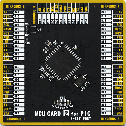
Type
8th Generation
Architecture
PIC
MCU Memory (KB)
64
Silicon Vendor
Microchip
Pin count
80
RAM (Bytes)
3862
Used MCU Pins
mikroBUS™ mapper
Take a closer look
Click board™ Schematic

Step by step
Project assembly

Start by selecting your development board and Click board™. Begin with the UNI-DS v8 as your development board.


Track your results in real time
Application Output
1. Application Output - In Debug mode, the 'Application Output' window enables real-time data monitoring, offering direct insight into execution results. Ensure proper data display by configuring the environment correctly using the provided tutorial.

2. UART Terminal - Use the UART Terminal to monitor data transmission via a USB to UART converter, allowing direct communication between the Click board™ and your development system. Configure the baud rate and other serial settings according to your project's requirements to ensure proper functionality. For step-by-step setup instructions, refer to the provided tutorial.

3. Plot Output - The Plot feature offers a powerful way to visualize real-time sensor data, enabling trend analysis, debugging, and comparison of multiple data points. To set it up correctly, follow the provided tutorial, which includes a step-by-step example of using the Plot feature to display Click board™ readings. To use the Plot feature in your code, use the function: plot(*insert_graph_name*, variable_name);. This is a general format, and it is up to the user to replace 'insert_graph_name' with the actual graph name and 'variable_name' with the parameter to be displayed.

Software Support
Library Description
This library contains API for PIR Click driver.
Key functions:
pir_get_adc- Reading 12bit ADC valuepir_reg_read- Reading registerpir_get_mili_volt- Reading ADC data in mili Volts
Open Source
Code example
The complete application code and a ready-to-use project are available through the NECTO Studio Package Manager for direct installation in the NECTO Studio. The application code can also be found on the MIKROE GitHub account.
/*!
 * \file
 * \brief Pir Click example
 *
 * # Description
 * This application which generates a voltage when exposed to infrared radiation.
 *
 * The demo application is composed of two sections :
 *
 * ## Application Init
 * Initializes device.
 *
 * ## Application Task
 * Reads ADC data, converts it to miliVolts and logs scaled value in miliVolts.
 *
 * \author MikroE Team
 *
 */
// ------------------------------------------------------------------- INCLUDES

#include "board.h"
#include "log.h"
#include "pir.h"

// ------------------------------------------------------------------ VARIABLES

static pir_t pir;
static log_t logger;

// ------------------------------------------------------ APPLICATION FUNCTIONS

void application_init ( void )
{
    log_cfg_t log_cfg;
    pir_cfg_t cfg;

    /**
     * Logger initialization.
     * Default baud rate: 115200
     * Default log level: LOG_LEVEL_DEBUG
     * @note If USB_UART_RX and USB_UART_TX
     * are defined as HAL_PIN_NC, you will
     * need to define them manually for log to work.
     * See @b LOG_MAP_USB_UART macro definition for detailed explanation.
     */
    LOG_MAP_USB_UART( log_cfg );
    log_init( &logger, &log_cfg );
    log_info( &logger, "---- Application Init ----" );

    //  Click initialization.

    pir_cfg_setup( &cfg );
    PIR_MAP_MIKROBUS( cfg, MIKROBUS_1 );
    pir_init( &pir, &cfg );
}

void application_task ( void )
{
    uint16_t adc_val;
    float map_out;

    adc_val = pir_get_adc( &pir );
    map_out = pir_scale_results( &pir, adc_val, 0, 3303 );

    log_printf( &logger, " Voltage: %.2f  miliVolts \r\n", map_out);

    Delay_ms ( 500 );
}

int main ( void )
{
    /* Do not remove this line or clock might not be set correctly. */
    #ifdef PREINIT_SUPPORTED
    preinit();
    #endif

    application_init( );

    for ( ; ; )
    {
        application_task( );
    }

    return 0;
}

// ------------------------------------------------------------------------ END


