Maintain the perfect balance in temperature control with PTMP4718 and STM32L4A6RG
Your vigilant guardian against extremes

Published Nov 15, 2023
Click board™
Temp Alarm Click
Dev. board
Fusion for ARM v8
Compiler
NECTO Studio
MCU
STM32L4A6RG
With our temperature sensor, you can alarm the chill and sound the heat, ensuring that your space is always in the comfort zone. It's the perfect solution for reliable and precise temperature monitoring.
A
A
Hardware Overview
How does it work?
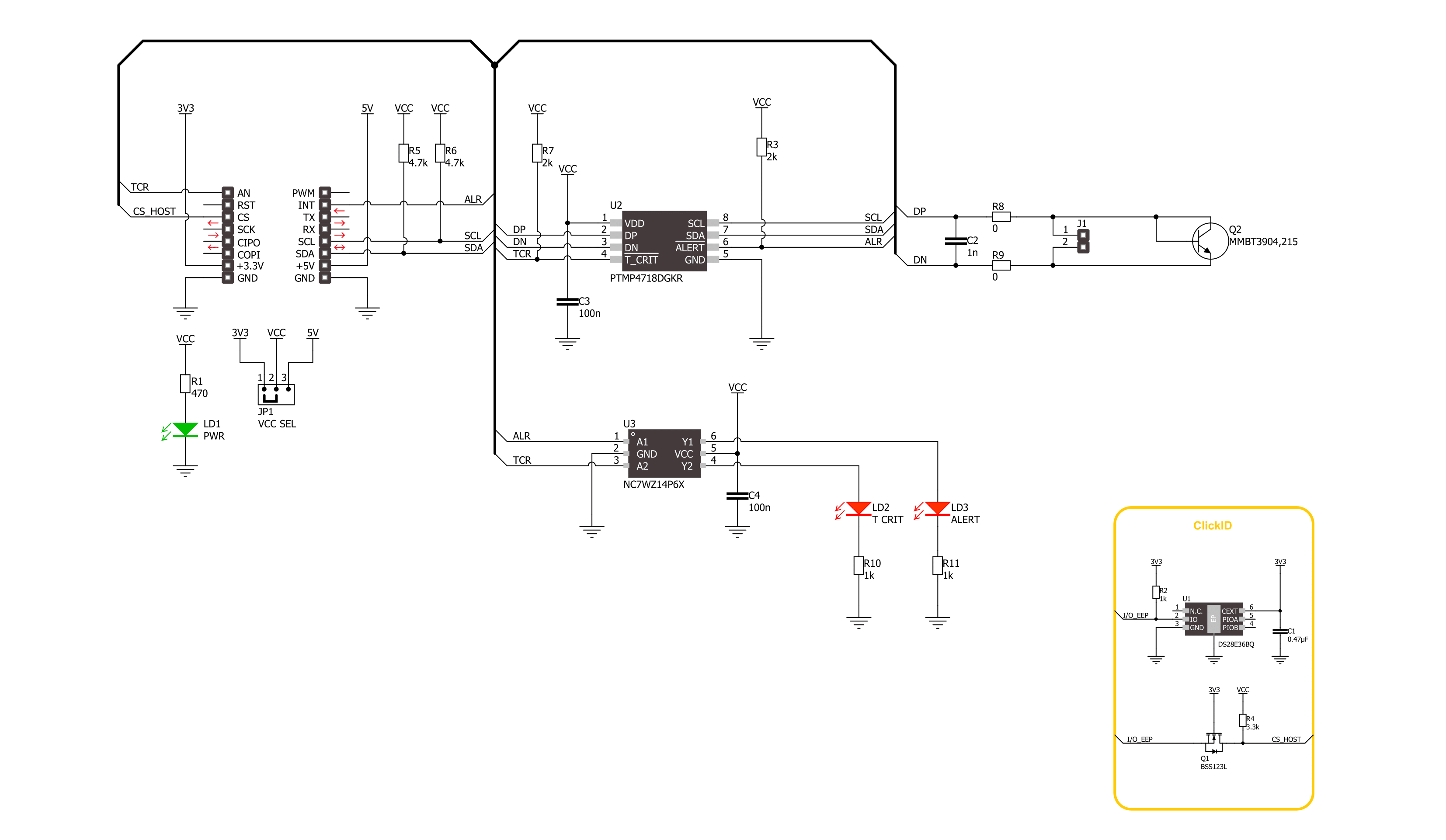
Temp Alert Click is based on the PTMP4718, a high-accuracy remote and local temperature sensor from Texas Instruments. It has 1°C accuracy for both the local and the remote channels. The resolution is better for the remote channel (0.125°C compared to the local 1°C). The sensor has a remote diode fault detection, low power consumption, programmable alert limits, and series resistance cancellation. Depending on the application, it can work in an interrupt or comparator mode. In both modes, the alert is asserted at the end of a conversion cycle if the measured temperature exceeds a High Alert Limit or goes below a Low Alert Limit defined in the limit thresholds. It can also work in a shutdown and a continuous conversion mode. The local temperature resolution is 8-bit in a -40 to 125°C
range. The remote temperature accuracy is 11-bit at -55 to 125°C and optimized for a diode-connected MMBT3904 transistor. Temp Alert Click is equipped with this NPN switching transistor from NXP Semiconductor that acts as a remote temperature sensor. There are DN and DP connectors as positive and negative connections for remote sensors. If you do not intend to use the remote temperature sensors at all, you should connect those DP and DN. In case of noise, you can add a 470pF capacitor between DP and DN pins. Temp Alert Click uses a standard 2-Wire U2C interface to communicate with the host MCU, supporting clock frequencies of up to 1MHz. The critical TCR pin will alert the critical temperature, with a threshold set by two 2K resistors to 77°C. According to a datasheet table, you can set this
value by replacing the resistors to up to 125°C. The critical temperature is considered when the temperature exceeds the high or low alert limits. The alert ALR pin is asserted when those temperatures reach the limits. The visual presentation of those two conditions is presented over the NC7WZ14, a Schmitt trigger from ON Semiconductor, which turns ON the T CRIT and ALERT red LEDs. This Click board™ can operate with either 3.3V or 5V logic voltage levels selected via the VCC SEL jumper. This way, both 3.3V and 5V capable MCUs can use the communication lines properly. Also, this Click board™ comes equipped with a library containing easy-to-use functions and an example code that can be used as a reference for further development.

Features overview
Development board
Fusion for ARM v8 is a development board specially designed for the needs of rapid development of embedded applications. It supports a wide range of microcontrollers, such as different ARM® Cortex®-M based MCUs regardless of their number of pins, and a broad set of unique functions, such as the first-ever embedded debugger/programmer over WiFi. The development board is well organized and designed so that the end-user has all the necessary elements, such as switches, buttons, indicators, connectors, and others, in one place. Thanks to innovative manufacturing technology, Fusion for ARM v8 provides a fluid and immersive working experience, allowing access anywhere and under any
circumstances at any time. Each part of the Fusion for ARM v8 development board contains the components necessary for the most efficient operation of the same board. An advanced integrated CODEGRIP programmer/debugger module offers many valuable programming/debugging options, including support for JTAG, SWD, and SWO Trace (Single Wire Output)), and seamless integration with the Mikroe software environment. Besides, it also includes a clean and regulated power supply module for the development board. It can use a wide range of external power sources, including a battery, an external 12V power supply, and a power source via the USB Type-C (USB-C) connector.
Communication options such as USB-UART, USB HOST/DEVICE, CAN (on the MCU card, if supported), and Ethernet is also included. In addition, it also has the well-established mikroBUS™ standard, a standardized socket for the MCU card (SiBRAIN standard), and two display options for the TFT board line of products and character-based LCD. Fusion for ARM v8 is an integral part of the Mikroe ecosystem for rapid development. Natively supported by Mikroe software tools, it covers many aspects of prototyping and development thanks to a considerable number of different Click boards™ (over a thousand boards), the number of which is growing every day.

Microcontroller Overview
MCU Card / MCU
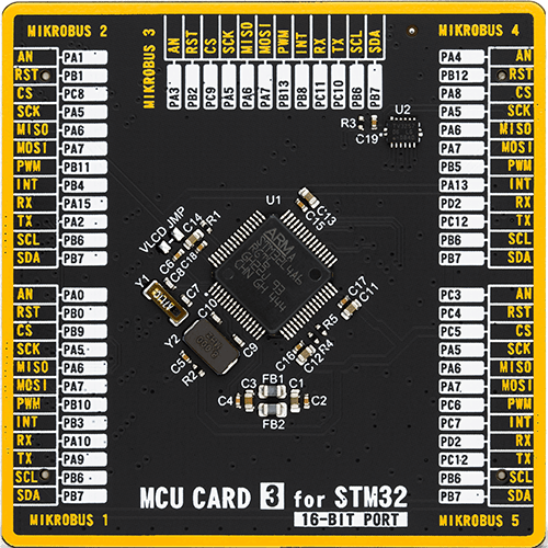
Type
8th Generation
Architecture
ARM Cortex-M4
MCU Memory (KB)
1024
Silicon Vendor
STMicroelectronics
Pin count
64
RAM (Bytes)
327680
Used MCU Pins
mikroBUS™ mapper
Take a closer look
Click board™ Schematic
Step by step
Project assembly

Start by selecting your development board and Click board™. Begin with the Fusion for ARM v8 as your development board.


Track your results in real time
Application Output
1. Application Output - In Debug mode, the 'Application Output' window enables real-time data monitoring, offering direct insight into execution results. Ensure proper data display by configuring the environment correctly using the provided tutorial.

2. UART Terminal - Use the UART Terminal to monitor data transmission via a USB to UART converter, allowing direct communication between the Click board™ and your development system. Configure the baud rate and other serial settings according to your project's requirements to ensure proper functionality. For step-by-step setup instructions, refer to the provided tutorial.

3. Plot Output - The Plot feature offers a powerful way to visualize real-time sensor data, enabling trend analysis, debugging, and comparison of multiple data points. To set it up correctly, follow the provided tutorial, which includes a step-by-step example of using the Plot feature to display Click board™ readings. To use the Plot feature in your code, use the function: plot(*insert_graph_name*, variable_name);. This is a general format, and it is up to the user to replace 'insert_graph_name' with the actual graph name and 'variable_name' with the parameter to be displayed.

Software Support
Library Description
This library contains API for Temp Alarm Click driver.
Key functions:
tempalarm_write_reg- Temp Alarm register writing function.tempalarm_read_remote_temperature- Temp Alarm remote sensor read temperature function.tempalarm_set_alarm_high_limit- Temp Alarm remote sensor set limit high temperature function.
Open Source
Code example
The complete application code and a ready-to-use project are available through the NECTO Studio Package Manager for direct installation in the NECTO Studio. The application code can also be found on the MIKROE GitHub account.
/*!
 * @file main.c
 * @brief Temp Alarm Click example
 *
 * # Description
 * This example demonstrates the use of Temp Alarm Click board by reading and displaying
 * the temperature measurements and monitoring it.
 *
 * The demo application is composed of two sections :
 *
 * ## Application Init
 * Initializes the driver and sets the Local sensor critical temperature at 30 degC with hysteresis of 1 degC,
 * and Remote sensor alarm temperature at 30 degC.
 *
 * ## Application Task
 * Reads the temperature measurement in degrees Celsius and displays the results on the USB UART
 * approximately once per second. Monitoring alarm and critical state.
 *
 * @author Stefan Ilic
 *
 */

#include "board.h"
#include "log.h"
#include "tempalarm.h"

static tempalarm_t tempalarm;
static log_t logger;

void application_init ( void )
{
    log_cfg_t log_cfg;  /**< Logger config object. */
    tempalarm_cfg_t tempalarm_cfg;  /**< Click config object. */

    /**
     * Logger initialization.
     * Default baud rate: 115200
     * Default log level: LOG_LEVEL_DEBUG
     * @note If USB_UART_RX and USB_UART_TX
     * are defined as HAL_PIN_NC, you will
     * need to define them manually for log to work.
     * See @b LOG_MAP_USB_UART macro definition for detailed explanation.
     */
    LOG_MAP_USB_UART( log_cfg );
    log_init( &logger, &log_cfg );
    log_info( &logger, " Application Init " );

    // Click initialization.
    tempalarm_cfg_setup( &tempalarm_cfg );
    TEMPALARM_MAP_MIKROBUS( tempalarm_cfg, MIKROBUS_1 );
    if ( I2C_MASTER_ERROR == tempalarm_init( &tempalarm, &tempalarm_cfg ) )
    {
        log_error( &logger, " Communication init." );
        for ( ; ; );
    }

    if ( TEMPALARM_ERROR == tempalarm_default_cfg ( &tempalarm ) )
    {
        log_error( &logger, " Default configuration." );
        for ( ; ; );
    }

    log_info( &logger, " Application Task " );
}

void application_task ( void )
{
    uint8_t flag_data = 0;
    int8_t local_temp = 0;
    float remote_temp = 0;
    tempalarm_get_alarms( &tempalarm, &flag_data );
    if ( TEMPALARM_ADC_BUSY_MASK != ( TEMPALARM_ADC_BUSY_MASK & flag_data ) )
    {
        tempalarm_read_temperature( &tempalarm, &local_temp );
        tempalarm_read_remote_temp( &tempalarm, &remote_temp );
        log_printf( &logger, " Local temperature : %d degC \r\n" , ( int16_t ) local_temp );
        log_printf( &logger, " Remote temperature : %.3f degC \r\n" , remote_temp );
        log_printf( &logger, " -------------------------------- \r\n" );
    }
    if ( TEMPALARM_PIN_STATE_LOW == tempalarm_get_alr_pin( &tempalarm ) )
    {
        log_printf( &logger, " Alarm is on, remote temperature  \r\n" );
        log_printf( &logger, "      is higher then 30 degC      \r\n" );
        log_printf( &logger, " -------------------------------- \r\n" );
    }
    if ( TEMPALARM_PIN_STATE_LOW == tempalarm_get_tcr_pin( &tempalarm ) )
    {
        log_printf( &logger, " Alarm is on, local temperature  \r\n" );
        log_printf( &logger, "      is higher then 30 degC      \r\n" );
        log_printf( &logger, " -------------------------------- \r\n" );
    }
    Delay_ms ( 1000 );
}

int main ( void )
{
    /* Do not remove this line or clock might not be set correctly. */
    #ifdef PREINIT_SUPPORTED
    preinit();
    #endif

    application_init( );

    for ( ; ; )
    {
        application_task( );
    }

    return 0;
}

// ------------------------------------------------------------------------ END
Additional Support
Resources
Category:Temperature & humidity


