Make a secure connection between interfaces with SC18IS602B and TM4C123GH6PZ
I2C Meets SPI: The revolutionary interface bridge solution!

Published Sep 21, 2023
Click board™
I2C to SPI Click
Dev. board
Fusion for Tiva v8
Compiler
NECTO Studio
MCU
TM4C123GH6PZ
Transform your projects with interface precision, as our bridge technology allows you to bridge the gap between I2C and SPI, optimizing data exchange, reducing complexity, and enhancing compatibility within your electronic applications
A
A
Hardware Overview
How does it work?
I2C to SPI Click is based on two SC18IS602B, an I2C-bus to SPI bridge from NXP Semiconductor. This IC bridges the data communication between the two interfaces, offering many additional features, such as the programmable I/O, internal oscillator option, active low interrupt output, low power mode, and more. The SC18IS602B operates as an I2C-bus slave-transmitter or slave-receiver and an SPI master. The SC18IS602B controls all the SPI bus-specific sequences, protocol, and timing. It also has its own internal oscillator, and it supports SPI chip select output that may be configured as GPIO when not used. This allows the software to be easily written or ported from another platform. The I2C to SPI Click provides a byte-oriented I2C-bus interface that supports data transfers up to 400 kHz. When the I2C-bus master is reading data from the click board™, the device will be a slave-transmitter. It also can be a slave-receiver when the I2C-bus master is sending data. The SC18IS602B acts as an I2C-bus master at no time. However, it does have the ability to hold the SCL
line LOW between bytes to complete its internal processes. A slave address of the SC18IS602B is comprised of a fixed and a programmable part. The programmable part of the slave address enables the maximum possible number of such devices to be connected to the I2C-bus. Since the SC18IS602B has three programmable address bits (defined by the A2, A1, and A0 pins), it is possible to have eight of these devices on the same bus. Therefore, this Click board™ is equipped with three SMD jumpers, grouped under the ADDR SEL label, used to select the I2C slave address. By moving the jumpers at the desired position, the user can select the address used for the communication with the host MCU. The #RESET pin performs the hardware reset of the SC18IS602B IC. The #RESET pin is routed to the mikroBUS™ RST pin and it is active LOW. The #INT allows the host MCU to receive an interrupt from the SC18IS602B IC. An interrupt is generated by the SC18IS602B after any SPI transmission has been completed. Therefore, the #INT of the
SC18IS602B is routed to the INT pin of the mikroBUS™ socket. The interrupt can be cleared (INT pin HIGH) by sending a ‘Clear Interrupt’ command, although It is not necessary. This allows more optimized software (firmware) to be written, as the host MCU does not have to continuously poll the LSR register to see if any interrupt needs to be serviced. The datasheet of the SC18IS602B offers more information about using and configuring the SC18IS602B IC. However, the Click board™ is supported by a mikroSDK library, offering functions that simplify the prototyping and firmware development. This Click board™ can be operated only with a 3.3V logic voltage level. The board must perform appropriate logic voltage level conversion before using MCUs with different logic levels. Also, it comes equipped with a library containing functions and an example code that can be used as a reference for further development.


Features overview
Development board
Fusion for TIVA v8 is a development board specially designed for the needs of rapid development of embedded applications. It supports a wide range of microcontrollers, such as different 32-bit ARM® Cortex®-M based MCUs from Texas Instruments, regardless of their number of pins, and a broad set of unique functions, such as the first-ever embedded debugger/programmer over a WiFi network. The development board is well organized and designed so that the end-user has all the necessary elements, such as switches, buttons, indicators, connectors, and others, in one place. Thanks to innovative manufacturing technology, Fusion for TIVA v8 provides a fluid and immersive working experience, allowing access
anywhere and under any circumstances at any time. Each part of the Fusion for TIVA v8 development board contains the components necessary for the most efficient operation of the same board. An advanced integrated CODEGRIP programmer/debugger module offers many valuable programming/debugging options, including support for JTAG, SWD, and SWO Trace (Single Wire Output)), and seamless integration with the Mikroe software environment. Besides, it also includes a clean and regulated power supply module for the development board. It can use a wide range of external power sources, including a battery, an external 12V power supply, and a power source via the USB Type-C (USB-C) connector.
Communication options such as USB-UART, USB HOST/DEVICE, CAN (on the MCU card, if supported), and Ethernet is also included. In addition, it also has the well-established mikroBUS™ standard, a standardized socket for the MCU card (SiBRAIN standard), and two display options for the TFT board line of products and character-based LCD. Fusion for TIVA v8 is an integral part of the Mikroe ecosystem for rapid development. Natively supported by Mikroe software tools, it covers many aspects of prototyping and development thanks to a considerable number of different Click boards™ (over a thousand boards), the number of which is growing every day.

Microcontroller Overview
MCU Card / MCU
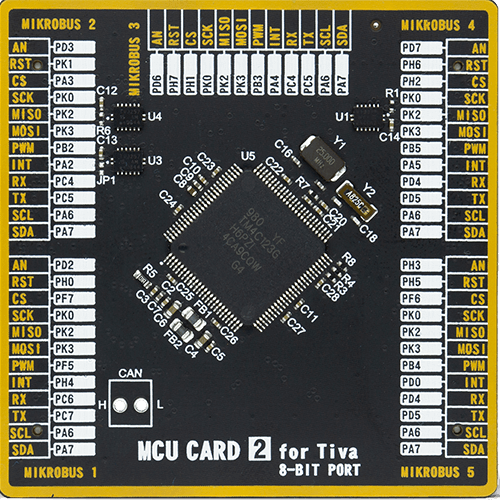
Type
8th Generation
Architecture
ARM Cortex-M4
MCU Memory (KB)
256
Silicon Vendor
Texas Instruments
Pin count
100
RAM (Bytes)
32768
Used MCU Pins
mikroBUS™ mapper
Take a closer look
Click board™ Schematic

Step by step
Project assembly

Start by selecting your development board and Click board™. Begin with the Fusion for Tiva v8 as your development board.


Software Support
Library Description
This library contains API for I2C to SPI Click driver.
Key functions:
i2ctospi_spi_write_byte- Function SPI write the byte of data to the targeted 8-bit register address of the SC18IS602B I2C-bus to SPI bridge on the I2C to SPI Clicki2ctospi_spi_read_byte- Function SPI read the byte of data from the targeted 8-bit register address of the SC18IS602B I2C-bus to SPI bridge on the I2C to SPI Clicki2ctospi_clear_interrupt- Function clear interrupt is generated by the SC18IS602B after any SPI transmission has been completed
Open Source
Code example
The complete application code and a ready-to-use project are available through the NECTO Studio Package Manager for direct installation in the NECTO Studio. The application code can also be found on the MIKROE GitHub account.
/*!
 * \file
 * \brief I2cToSpi Click example
 *
 * # Description
 * I2C to SPi Click allows serving as an interface between a standard I2C-bus of a microcontroller
 * and an SPi bus, which allows the microcontroller to communicate directly with SPi devices
 * through its I2C-bus. By offering an I2C-bus slave-transmitter or slave-receiver and SPI master,
 * this Click controls all the SPi bus-specific sequences, protocol, and timing. It also has its own
 * internal oscillator, and it supports the SPi chip select output that may be configured as GPIO when not used.
 *
 * The demo application is composed of two sections :
 *
 * ## Application Init
 * Initialization driver enable's - I2C,
 * hardware reset, SS0 ( CS ) configured to be used as slave select outputs, set the configuration of SPI:
 * order MSB first, clock Idle low, leading-edge transition, SPI clock rate to 115kHz,
 * set SPI EEPROM write enable SS0, clear  interrupt,
 * clear RT5 register, sets starting time: hours, minutes and seconds ( enable counting ), also write log.
 *
 * ## Application Task
 * This is an example which demonstrates the use of RTC 5 Click is wired to I2C to SPI Click board.
 * I2C to SPI Click communicates with register via the I2C interface,
 * serve as an interface between a standard I2C-bus of a microcontroller and an SPI bus.
 * RTC 5 Click communicates with register via SPI interface.
 * In this examples, we display RTC time which we received reading from the target register
 * address of MCP79510 chip on RTC 5 Click board via I2C interface of I2C to SPI Click board.
 * Results are being sent to the Usart Terminal where you can track their changes.
 * All data logs write on usb uart changes for every 1 sec.
 *
 * *note:*
 * <pre>
 * Additional Functions :
 *  - void display_log_uart( uint8_t value ) - Write the value of time or date as a two-digit number.
 *  - void rtc5_clear( i2ctospi_t *ctx, i2ctospi_spi_t *spi ) - Clear RTCC and SRAM memory of RTC 5 Click.
 *  - void rtc5_set_time_seconds( i2ctospi_t *ctx, i2ctospi_spi_t *spi, uint8_t seconds ) - Set the seconds and enable counting.
 *  - uint8_t rtc5_get_time_seconds( i2ctospi_t *ctx, i2ctospi_spi_t *spi ) - Get the seconds.
 *  - void rtc5_set_time_minutes( uint8_t minutes ) - Set the minutes.
 *  - uint8_t rtc5_get_time_minutes( i2ctospi_t *ctx, i2ctospi_spi_t *spi ) - Get the minutes.
 *  - void rtc5_set_time_hours( i2ctospi_t *ctx, i2ctospi_spi_t *spi, uint8_t hours ) - Set the hours.
 *  - uint8_t rtc5_get_time_hours( i2ctospi_t *ctx, i2ctospi_spi_t *spi ) - Get the hours.
 * </pre>
 *
 * \author MikroE Team
 *
 */
// ------------------------------------------------------------------- INCLUDES

#include "board.h"
#include "log.h"
#include "i2ctospi.h"

// ------------------------------------------------------------------ VARIABLES

static i2ctospi_t i2ctospi;
static i2ctospi_spi_t i2ctospi_spi;
static i2ctospi_gpio_t i2ctospi_gpio;
static log_t logger;

static uint8_t time_hours;
static uint8_t time_minutes;
static uint8_t time_seconds;
static uint8_t time_seconds_new = 0xFF;

// ------------------------------------------------------- ADDITIONAL FUNCTIONS

void display_log_uart ( uint8_t value )
{
    log_printf( &logger, " %d%d ", ( uint16_t )( value / 10 ), ( uint16_t )( value % 10 ) );
}

void rtc5_clear ( i2ctospi_t *ctx, i2ctospi_spi_t *spi )
{
    uint8_t reg_add;

    spi->slave_device = I2CTOSPI_SLAVEDEVICE_SS0;
    spi->function_id = I2CTOSPI_RTC5_COMMAND_WRITE;
    spi->reg_addr = reg_add;

    for ( reg_add = 0; reg_add < 0x20; reg_add++ )
    {
        i2ctospi_spi_write_byte( ctx, spi, 0x00 );
        Delay_1us( );
    }

    spi->reg_addr = I2CTOSPI_RTC5_COMMAND_CLEAR;
    i2ctospi_spi_write_byte( ctx, spi, 0x00 );

    i2ctospi_clear_interrupt( ctx );
}

void rtc5_set_time_seconds ( i2ctospi_t *ctx, i2ctospi_spi_t *spi, uint8_t seconds )
{
    uint8_t ones;
    uint8_t tens;
    uint8_t temp;

    ones = 0x00;
    tens = 0x00;

    seconds %= 60;

    ones = seconds % 10;

    tens = ( seconds / 10 ) << 4;

    temp = tens | ones;
    temp |= I2CTOSPI_RTC5_COMMAND_ENABLE_COUNTING;

    spi->slave_device = I2CTOSPI_SLAVEDEVICE_SS0;
    spi->function_id = I2CTOSPI_RTC5_COMMAND_WRITE;
    spi->reg_addr = I2CTOSPI_RTC5_REG_TIME_SEC;

    i2ctospi_spi_write_byte( ctx, spi, temp );
}

uint8_t rtc5_get_time_seconds ( i2ctospi_t *ctx, i2ctospi_spi_t *spi )
{
    uint8_t ones;
    uint8_t tens;
    uint8_t result_sec;
    uint8_t temp;

    spi->slave_device = I2CTOSPI_SLAVEDEVICE_SS0;
    spi->function_id = I2CTOSPI_RTC5_COMMAND_READ;
    spi->reg_addr = I2CTOSPI_RTC5_REG_TIME_SEC;

    temp = i2ctospi_spi_read_byte( ctx, spi );

    ones = temp & 0x0F;

    tens = ( temp & 0x70 ) >> 4;

    result_sec = ( 10 * tens ) + ones;

    return result_sec;
}

void rtc5_set_time_minutes ( i2ctospi_t *ctx, i2ctospi_spi_t *spi, uint8_t minutes )
{
    uint8_t ones;
    uint8_t tens;
    uint8_t temp;

    ones = 0x00;
    tens = 0x00;

    minutes %= 60;

    ones = minutes % 10;

    tens = ( minutes / 10 ) << 4;

    temp = tens | ones;

    spi->slave_device = I2CTOSPI_SLAVEDEVICE_SS0;
    spi->function_id = I2CTOSPI_RTC5_COMMAND_WRITE;
    spi->reg_addr = I2CTOSPI_RTC5_REG_TIME_MIN;

    i2ctospi_spi_write_byte( ctx, spi, temp );
}

uint8_t rtc5_get_time_minutes ( i2ctospi_t *ctx, i2ctospi_spi_t *spi )
{
    uint8_t ones;
    uint8_t tens;
    uint8_t result_min;
    uint8_t temp;

    spi->slave_device = I2CTOSPI_SLAVEDEVICE_SS0;
    spi->function_id = I2CTOSPI_RTC5_COMMAND_READ;
    spi->reg_addr = I2CTOSPI_RTC5_REG_TIME_MIN;

    temp = i2ctospi_spi_read_byte( ctx, spi );

    ones = temp & 0x0F;

    tens = ( temp & 0x70 ) >> 4;

    result_min = ( 10 * tens ) + ones;

    return result_min;
}

void rtc5_set_time_hours ( i2ctospi_t *ctx, i2ctospi_spi_t *spi, uint8_t hours )
{
    uint8_t ones;
    uint8_t tens;
    uint8_t temp;

    ones = 0x00;
    tens = 0x00;

    hours %= 24;

    ones = hours % 10;

    tens = ( hours / 10 ) << 4;

    temp = tens | ones;

    spi->slave_device = I2CTOSPI_SLAVEDEVICE_SS0;
    spi->function_id = I2CTOSPI_RTC5_COMMAND_WRITE;
    spi->reg_addr = I2CTOSPI_RTC5_REG_TIME_HOUR,

    i2ctospi_spi_write_byte( ctx, spi, temp );
}

uint8_t rtc5_get_time_hours ( i2ctospi_t *ctx, i2ctospi_spi_t *spi )
{
    uint8_t ones;
    uint8_t tens;
    uint8_t result_hours;
    uint8_t temp;

    spi->slave_device = I2CTOSPI_SLAVEDEVICE_SS0;
    spi->function_id = I2CTOSPI_RTC5_COMMAND_READ;
    spi->reg_addr = I2CTOSPI_RTC5_REG_TIME_HOUR;

    temp = i2ctospi_spi_read_byte( ctx, spi );

    ones = temp & 0x0F;

    tens = ( temp & 0x30 ) >> 4;

    result_hours = ( 10 * tens ) + ones;

    return result_hours;
}

// ------------------------------------------------------ APPLICATION FUNCTIONS

void application_init ( void )
{
    log_cfg_t log_cfg;
    i2ctospi_cfg_t cfg;

    /**
     * Logger initialization.
     * Default baud rate: 115200
     * Default log level: LOG_LEVEL_DEBUG
     * @note If USB_UART_RX and USB_UART_TX
     * are defined as HAL_PIN_NC, you will
     * need to define them manually for log to work.
     * See @b LOG_MAP_USB_UART macro definition for detailed explanation.
     */
    LOG_MAP_USB_UART( log_cfg );
    log_init( &logger, &log_cfg );
    log_info( &logger, "---- Application Init ----" );

    //  Click initialization.

    i2ctospi_cfg_setup( &cfg );
    I2CTOSPI_MAP_MIKROBUS( cfg, MIKROBUS_1 );
    i2ctospi_init( &i2ctospi, &cfg );

    i2ctospi_default_cfg( &i2ctospi );

    //Set Time :  23h 59m 48s
    rtc5_clear( &i2ctospi, &i2ctospi_spi );
    rtc5_set_time_hours( &i2ctospi, &i2ctospi_spi, 23 );
    Delay_1ms( );
    rtc5_set_time_minutes( &i2ctospi, &i2ctospi_spi, 59 );
    Delay_1ms( );
    rtc5_set_time_seconds( &i2ctospi, &i2ctospi_spi, 48 );
    Delay_1ms( );
}

void application_task ( void )
{
    time_seconds = rtc5_get_time_seconds( &i2ctospi, &i2ctospi_spi );
    Delay_1ms( );
    time_minutes = rtc5_get_time_minutes( &i2ctospi, &i2ctospi_spi );
    Delay_1ms( );
    time_hours = rtc5_get_time_hours( &i2ctospi, &i2ctospi_spi );
    Delay_1ms( );

    if ( time_seconds_new != time_seconds )
    {
        log_printf( &logger, " Time :  " );

        display_log_uart( time_hours );
        log_printf( &logger, ":" );

        display_log_uart( time_minutes );
        log_printf( &logger, ":" );

        display_log_uart( time_seconds );
        log_printf( &logger, "\r\n" );

        log_printf( &logger, "------------------\r\n" );

        time_seconds_new = time_seconds;
    }

    Delay_1ms( );
}

int main ( void )
{
    /* Do not remove this line or clock might not be set correctly. */
    #ifdef PREINIT_SUPPORTED
    preinit();
    #endif

    application_init( );

    for ( ; ; )
    {
        application_task( );
    }

    return 0;
}


// ------------------------------------------------------------------------ END
Additional Support
Resources
Category:I2C


