Master motor speed control with Si8711CC and STM32F410RB
PWM precision meets motor control

Published Jul 25, 2023
Click board™
PWM driver Click
Dev. board
UNI-DS v8
Compiler
NECTO Studio
MCU
STM32F410RB
Unlock speed control possibilities with our PWM-controlled DC motor solution
A
A
Hardware Overview
How does it work?
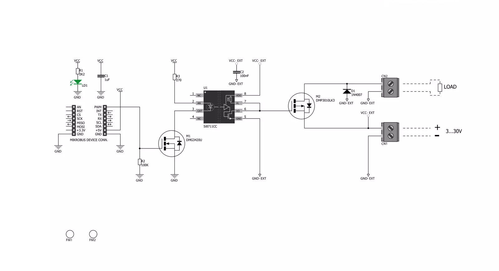
PWM driver Click is based on the Si8711CC, a 5kV LED emulator input, open collector output isolator from Skyworks. Compared to the optocouplers, the Si8711CC is more resistant to temperature, age, and forward current effects. It has a longer service life, higher common-mode transient immunity, and more. The Si8711CC is based on proprietary CMOS isolation technology for low-power, high-speed operation and is resistant to wear-out effects that, in the case of optocouplers, degrade the performance. The Si8711CC features up to 5000VRMS isolation and 10kV surge protection, making it a perfect isolator. For controlling the devices, it is capable of data rates DC of up to 15Mbps, with a propagation delay of 30ns. The Si8711CC controls the loads over the DMP3010LK3,
a P-channel enhancement mode MOSFET from Diodes Incorporated. This fast-switching diode has ESD protected gate, low input capacitance, and low on-resistance, designed to maintain superior switching performance, making it ideal for high-efficiency power management applications. The PWM Driver Click comes with the screw terminals labeled LOAD (+END, -END) to connect the load, which the Si7811CC controls over the DMP3010LK3 diode, and EXT for external power supply. It is not recommended to use this Click board™ with loads over 50W as the MOSFET can get overheated; this, however, does not apply if the Click board™ is used as an ON/OFF switch. The PWM Driver Click is controlled by the host MCU by PWM pulses over the PWM pin of the mikroBUS™ socket. The PWM
pin does not have direct control over the Si8711CC but rather through the DMG3420U, an N-channel enhancement mode MOSFET from Diodes Incorporated. This diode shares many features with the one mentioned above, such as low on-resistance, low input capacitance, fast switching speed, and more. This Click board™ can be operated only with a 5V logic voltage level. The board must perform appropriate logic voltage level conversion before using MCUs with different logic levels. However, the Click board™ comes equipped with a library containing functions and an example code that can be used, as a reference, for further development.

Features overview
Development board
UNI-DS v8 is a development board specially designed for the needs of rapid development of embedded applications. It supports a wide range of microcontrollers, such as different STM32, Kinetis, TIVA, CEC, MSP, PIC, dsPIC, PIC32, and AVR MCUs regardless of their number of pins, and a broad set of unique functions, such as the first-ever embedded debugger/programmer over WiFi. The development board is well organized and designed so that the end-user has all the necessary elements, such as switches, buttons, indicators, connectors, and others, in one place. Thanks to innovative manufacturing technology, UNI-DS v8 provides a fluid and immersive working experience, allowing access anywhere and under any
circumstances at any time. Each part of the UNI-DS v8 development board contains the components necessary for the most efficient operation of the same board. An advanced integrated CODEGRIP programmer/debugger module offers many valuable programming/debugging options, including support for JTAG, SWD, and SWO Trace (Single Wire Output)), and seamless integration with the Mikroe software environment. Besides, it also includes a clean and regulated power supply module for the development board. It can use a wide range of external power sources, including a battery, an external 12V power supply, and a power source via the USB Type-C (USB-C) connector. Communication options such as USB-UART, USB
HOST/DEVICE, CAN (on the MCU card, if supported), and Ethernet is also included. In addition, it also has the well-established mikroBUS™ standard, a standardized socket for the MCU card (SiBRAIN standard), and two display options for the TFT board line of products and character-based LCD. UNI-DS v8 is an integral part of the Mikroe ecosystem for rapid development. Natively supported by Mikroe software tools, it covers many aspects of prototyping and development thanks to a considerable number of different Click boards™ (over a thousand boards), the number of which is growing every day.

Microcontroller Overview
MCU Card / MCU
Type
8th Generation
Architecture
ARM Cortex-M4
MCU Memory (KB)
128
Silicon Vendor
STMicroelectronics
Pin count
64
RAM (Bytes)
32768
Used MCU Pins
mikroBUS™ mapper
Take a closer look
Click board™ Schematic
Step by step
Project assembly

Start by selecting your development board and Click board™. Begin with the UNI-DS v8 as your development board.


Software Support
Library Description
This library contains API for PWM driver Click driver.
Key functions:
pwmdriver_set_duty_cycle- Generic sets PWM duty cyclepwmdriver_pwm_stop- Stop PWM modulepwmdriver_pwm_start- Start PWM module
Open Source
Code example
The complete application code and a ready-to-use project are available through the NECTO Studio Package Manager for direct installation in the NECTO Studio. The application code can also be found on the MIKROE GitHub account.
/*!
 * @file
 * @brief PwmDriver Click example
 *
 * # Description
 * This application is controls the speed DC motors.
 *
 * The demo application is composed of two sections :
 *
 * ## Application Init
 * Initialization driver enables - GPIO, PWM initialization set PWM duty cycle and PWM frequency,
 * start PWM, enable the engine, and start to write log.
 *
 * ## Application Task
 * This is an example that demonstrates the use of the PWM driver Click board.
 * This example shows the automatic control of PWM,
 * the first increases duty cycle and then the duty cycle is falling.
 * Results are being sent to the Usart Terminal where you can track their changes.
 *
 * *note:*
 * EXT PWR 3-30VDC
 *
 * @author Nikola Peric
 *
 */
// ------------------------------------------------------------------- INCLUDES

#include "board.h"
#include "log.h"
#include "pwmdriver.h"

// ------------------------------------------------------------------ VARIABLES

static pwmdriver_t pwmdriver;
static log_t logger;

// ------------------------------------------------------ APPLICATION FUNCTIONS

void application_init ( void )
{
    log_cfg_t log_cfg;
    pwmdriver_cfg_t cfg;

    /**
     * Logger initialization.
     * Default baud rate: 115200
     * Default log level: LOG_LEVEL_DEBUG
     * @note If USB_UART_RX and USB_UART_TX
     * are defined as HAL_PIN_NC, you will
     * need to define them manually for log to work.
     * See @b LOG_MAP_USB_UART macro definition for detailed explanation.
     */
    LOG_MAP_USB_UART( log_cfg );
    log_init( &logger, &log_cfg );
    log_info( &logger, "---- Application Init ----" );

    //  Click initialization.

    pwmdriver_cfg_setup( &cfg );
    PWMDRIVER_MAP_MIKROBUS( cfg, MIKROBUS_1 );
    pwmdriver_init( &pwmdriver, &cfg );
    Delay_ms ( 100 );

    log_printf( &logger, "   Initialization PWM  \r\n  " );
    pwmdriver_set_duty_cycle( &pwmdriver, 0.0 );
    pwmdriver_pwm_start( &pwmdriver );
    Delay_ms ( 1000 );
    log_info( &logger, "---- Application Task ----" );
}

void application_task ( void )
{
    static int8_t duty_cnt = 1;
    static int8_t duty_inc = 1;
    float duty = duty_cnt / 10.0;

    pwmdriver_set_duty_cycle ( &pwmdriver, duty );
    log_printf( &logger, "Duty: %d%%\r\n", ( uint16_t )( duty_cnt * 10 ) );
    Delay_ms ( 500 );

    if ( 10 == duty_cnt )
    {
        duty_inc = -1;
    }
    else if ( 0 == duty_cnt )
    {
        duty_inc = 1;
    }
    duty_cnt += duty_inc;
}

int main ( void )
{
    /* Do not remove this line or clock might not be set correctly. */
    #ifdef PREINIT_SUPPORTED
    preinit();
    #endif

    application_init( );

    for ( ; ; )
    {
        application_task( );
    }

    return 0;
}


// ------------------------------------------------------------------------ END


