Create your own N-PLC system for any IoT application, thanks to SM2400 and STM32F439ZG
Narrow-band Power Line Communication (N-PLC)

Published Nov 09, 2023
Click board™
N-PLC Click
Dev. board
UNI-DS v8
Compiler
NECTO Studio
MCU
STM32F439ZG
Revolutionize your connectivity strategy and cut expenses by leveraging your existing electrical infrastructure for seamless communication.
A
A
Hardware Overview
How does it work?
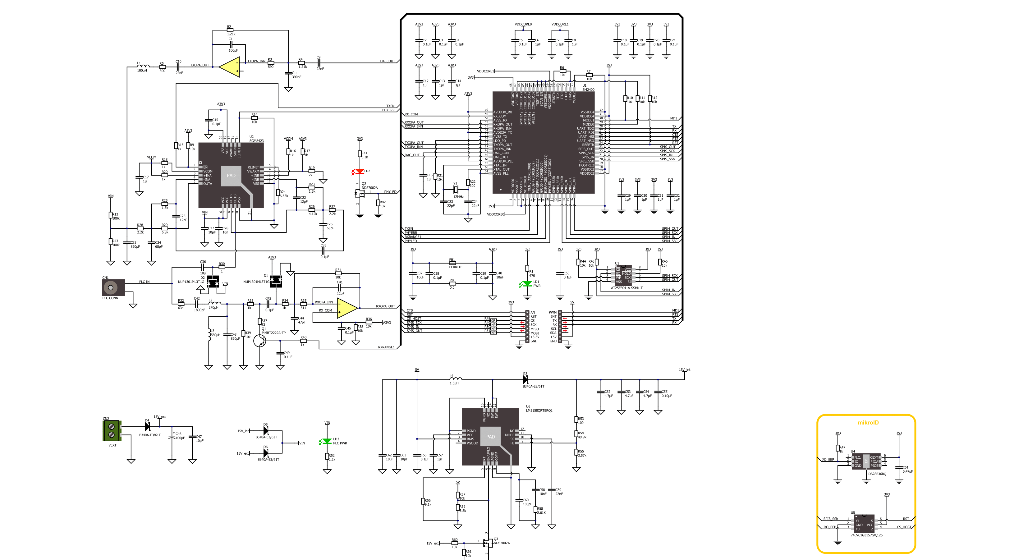
N-PLC Click is based on the SM2400, the ultimate Narrow-band Power Line Communication (N-PLC) modem from Semitech that combines cost-effective design optimized for PLC applications with a high level of programmability to address a multitude of communications schemes and evolving standards. The SM2400 system-on-chip (SoC) features a dual-core architecture for dedicated PHY signal processing and MAC layer functionality to guarantee superior communication performance while maintaining high flexibility and programmability for OFDM-based and other open standards and fully customized implementations. It has a set of firmware options implementing IEEE 1901.2 compliant PHY and MAC layers, a 6LoWPAN data link layer, PRIME, G3-PLC, and other special modes tailored for industrial IoT applications. The SM2400 combines the benefits of programmable architecture with power and efficiency by utilizing a DSP core configured specifically for N-PLC modulations and a dedicated 32-bit core that runs protocols. It contains a high-speed 256-bit AES-CCM engine to ensure standard compliance and secure communication, and all the necessary mixed-signal components, such as ADC, DAC, gain control and two OpAmp to deliver a cost-effective N-PLC system design for any application. In addition to the SM2400, this Click board™ also includes a PLC line driver, the SGM8423, a high efficiency, Class A/B, and a low distortion power line driver. It is optimized to accept a signal from a
Power Line Carrier modem, such as the SM2400, which is presented in the example code, where two such boards talk to each other in a transmitter/receiver configuration. Besides directly performing enable/shutdown control of the line driver, the SM2400 has one diagnostic signal that can indicate error conditions, such as overcurrent or overheating, reported by the line driver. In addition, it is also possible to supply high voltage (110/220VAC) as an input on the PLC CONN connector, which will be converted into a signal of the appropriate level via the N-PLC Wall Adapter, a simple yet very useful power line communication AC coupling circuit for safe and secure operation. The green PLC PWR LED signal that the N-PLC Wall Adapter is connected and powered. The SM2400 communicates with an MCU using the UART interface as its main one, with commonly used UART RX and TX pins and the optional hardware flow control pins UART CTS and RTS (Clear to Send and Ready to Send). The UART interface serves as the primary interface to a host, which can be an MCU or a converter, such as serial-to-USB. As an alternative to the UART interface, users also have at their disposal the lines of the SPI serial interface (to use this interface, it is necessary to populate the appropriate 0Ω resistors to activate the SPI lines). The SM2400 executes its firmware from internal memory, with the loaded code at a boot time. The SM2400 can boot either from an external SPI flash, the AT25FF041A, or from a host MCU via UART interface depending on
the logic state of the MD1 pin of the mikroBUS™ socket (0 - boot over UART interface that allows direct firmware download (boot from the host), 1 – boot from external SPI flash memory), with the host MCU being the Master. In addition, the SM2400 provides the possibility of a reset via the RST pin of the mikroBUS™ socket (asserting this pin causes full chip reset and reboot), as well as visual detection of the communication status via the red PHY LED, which is asserted when an incoming packet is detected. The power supply of this Click board™ is performed very simply, without any additional hardware configuration (depending on the power supply capability and the desired range). It is possible to power the board in two ways: internally and externally. By default, the board power will be provided internally over the LM5158 boost converter in the value of 15V, which is obtained from the 5V mikroBUS™ power rail. When applying an external power supply of 15VDC on the VEXT terminal, the N-PLC Click will automatically be powered from the external source thanks to the protection of the converter, which automatically recognizes the presence of the external power supply and gives it priority. This Click board™ can be operated only with a 3.3V logic voltage level. The board must perform appropriate logic voltage level conversion before using MCUs with different logic levels. Also, it comes equipped with a library containing functions and an example code that can be used as a reference for further development.

Features overview
Development board
UNI-DS v8 is a development board specially designed for the needs of rapid development of embedded applications. It supports a wide range of microcontrollers, such as different STM32, Kinetis, TIVA, CEC, MSP, PIC, dsPIC, PIC32, and AVR MCUs regardless of their number of pins, and a broad set of unique functions, such as the first-ever embedded debugger/programmer over WiFi. The development board is well organized and designed so that the end-user has all the necessary elements, such as switches, buttons, indicators, connectors, and others, in one place. Thanks to innovative manufacturing technology, UNI-DS v8 provides a fluid and immersive working experience, allowing access anywhere and under any
circumstances at any time. Each part of the UNI-DS v8 development board contains the components necessary for the most efficient operation of the same board. An advanced integrated CODEGRIP programmer/debugger module offers many valuable programming/debugging options, including support for JTAG, SWD, and SWO Trace (Single Wire Output)), and seamless integration with the Mikroe software environment. Besides, it also includes a clean and regulated power supply module for the development board. It can use a wide range of external power sources, including a battery, an external 12V power supply, and a power source via the USB Type-C (USB-C) connector. Communication options such as USB-UART, USB
HOST/DEVICE, CAN (on the MCU card, if supported), and Ethernet is also included. In addition, it also has the well-established mikroBUS™ standard, a standardized socket for the MCU card (SiBRAIN standard), and two display options for the TFT board line of products and character-based LCD. UNI-DS v8 is an integral part of the Mikroe ecosystem for rapid development. Natively supported by Mikroe software tools, it covers many aspects of prototyping and development thanks to a considerable number of different Click boards™ (over a thousand boards), the number of which is growing every day.

Microcontroller Overview
MCU Card / MCU
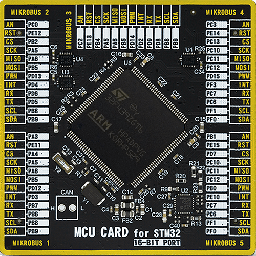
Type
8th Generation
Architecture
ARM Cortex-M4
MCU Memory (KB)
1024
Silicon Vendor
STMicroelectronics
Pin count
144
RAM (Bytes)
262144
You complete me!
Accessories
An assortement of compatible AC plugs for all parts of the world are also sold. Reliability is paramount when it comes to power supply units. That's why we opted to carry Sunny Power Supply units. Note that power supply units are sold without AC plugs. Depending on where you are in the world, or where you plan to be, we also offer a wide selection of compatible AC plugs.

MIKROE offers a wide range of AC plugs for our Wall Power Supply units compatible with standards from Europe, the USA, the UK, India, China, Brazil, Australia, South Africa, Korea, and Argentina.

Used MCU Pins
mikroBUS™ mapper
Take a closer look
Click board™ Schematic
Step by step
Project assembly

Start by selecting your development board and Click board™. Begin with the UNI-DS v8 as your development board.


Track your results in real time
Application Output
1. Application Output - In Debug mode, the 'Application Output' window enables real-time data monitoring, offering direct insight into execution results. Ensure proper data display by configuring the environment correctly using the provided tutorial.

2. UART Terminal - Use the UART Terminal to monitor data transmission via a USB to UART converter, allowing direct communication between the Click board™ and your development system. Configure the baud rate and other serial settings according to your project's requirements to ensure proper functionality. For step-by-step setup instructions, refer to the provided tutorial.

3. Plot Output - The Plot feature offers a powerful way to visualize real-time sensor data, enabling trend analysis, debugging, and comparison of multiple data points. To set it up correctly, follow the provided tutorial, which includes a step-by-step example of using the Plot feature to display Click board™ readings. To use the Plot feature in your code, use the function: plot(*insert_graph_name*, variable_name);. This is a general format, and it is up to the user to replace 'insert_graph_name' with the actual graph name and 'variable_name' with the parameter to be displayed.

Software Support
Library Description
This library contains API for N-PLC Click driver.
Key functions:
nplc_set_mode- This function sets operation mode to command or data.nplc_generic_write- This function writes a desired number of data bytes by using UART serial interface.nplc_generic_read- This function reads a desired number of data bytes by using UART serial interface.
Open Source
Code example
The complete application code and a ready-to-use project are available through the NECTO Studio Package Manager for direct installation in the NECTO Studio. The application code can also be found on the MIKROE GitHub account.
/*!
 * @file main.c
 * @brief N-PLC Click Example.
 *
 * # Description
 * This example demonstrates the use of an N-PLC Click boards by showing
 * the communication between the two Click boards configured as a receiver and transmitter.
 *
 * The demo application is composed of two sections :
 *
 * ## Application Init
 * Initializes the driver, resets the Click board to default config, displays the firmware version
 * and switches to data operation mode. After that displays the selected application mode
 * and sends an initial message in case of transmitter mode.
 *
 * ## Application Task
 * Reads all the received data and echoes them back to the transmitter. The received and echoed messages
 * will be displayed on the USB UART.
 *
 * @note
 * Once both devices are programmed, one as a receiver and the other as a transmitter, you will need to reset
 * the transmitter board in order to start the communication by sending an initial message.
 *
 * @author Stefan Filipovic
 *
 */

#include "board.h"
#include "log.h"
#include "nplc.h"

// Comment out the line below in order to switch the application mode to receiver
// #define DEMO_APP_TRANSMITTER

#define DEMO_TEXT_MESSAGE       "MikroE - N-PLC Click board"

#define PROCESS_BUFFER_SIZE     200
#define RSP_TIMEOUT_MS          20000

static nplc_t nplc;
static log_t logger;

static char app_buf[ PROCESS_BUFFER_SIZE ] = { 0 };
static int32_t app_buf_len = 0;

/**
 * @brief N-PLC clearing application buffer.
 * @details This function clears memory of application buffer and reset its length and counter.
 * @note None.
 */
static void nplc_clear_app_buf ( void );

/**
 * @brief N-PLC data reading function.
 * @details This function reads data from device and concatenates data to application buffer.
 * @return @li @c  0 - Read some data.
 *         @li @c -1 - Nothing is read or buffer overflow error.
 * See #err_t definition for detailed explanation.
 * @note None.
 */
static err_t nplc_process ( void );

/**
 * @brief N-PLC display response function.
 * @details This function checks if any data is received from device and displays it on the USB UART.
 * @return @li @c  0 - Read some data.
 *         @li @c -1 - Timeout error.
 * See #err_t definition for detailed explanation.
 * @note None.
 */
static err_t nplc_display_rsp ( void );

void application_init ( void )
{
    log_cfg_t log_cfg;  /**< Logger config object. */
    nplc_cfg_t nplc_cfg;  /**< Click config object. */

    /**
     * Logger initialization.
     * Default baud rate: 115200
     * Default log level: LOG_LEVEL_DEBUG
     * @note If USB_UART_RX and USB_UART_TX
     * are defined as HAL_PIN_NC, you will
     * need to define them manually for log to work.
     * See @b LOG_MAP_USB_UART macro definition for detailed explanation.
     */
    LOG_MAP_USB_UART( log_cfg );
    log_init( &logger, &log_cfg );
    log_info( &logger, " Application Init " );

    // Click initialization.
    nplc_cfg_setup( &nplc_cfg );
    NPLC_MAP_MIKROBUS( nplc_cfg, MIKROBUS_1 );
    if ( UART_ERROR == nplc_init( &nplc, &nplc_cfg ) )
    {
        log_error( &logger, " Communication init." );
        for ( ; ; );
    }
    nplc_process( );
    nplc_clear_app_buf( );

    log_printf( &logger, " - HW reset -\r\n" );
    nplc_hw_reset ( &nplc );
    nplc_display_rsp ( );

    log_printf( &logger, " - Go to command mode -\r\n" );
    nplc_set_mode ( &nplc, NPLC_MODE_COMMAND );
    nplc_display_rsp ( );

    log_printf( &logger, " - Factory reset -\r\n" );
    nplc_factory_reset ( &nplc );
    nplc_display_rsp ( );

    log_printf( &logger, " - Reboot -\r\n" );
    nplc_sw_reset ( &nplc );
    nplc_display_rsp ( );

    log_printf( &logger, " - Go to command mode -\r\n" );
    nplc_set_mode ( &nplc, NPLC_MODE_COMMAND );
    nplc_display_rsp ( );

    log_printf( &logger, " - Show firmware version -\r\n" );
    nplc_firmware_version ( &nplc );
    nplc_display_rsp ( );

    log_printf( &logger, " - Go to data mode -\r\n" );
    nplc_set_mode ( &nplc, NPLC_MODE_DATA );

#ifdef DEMO_APP_TRANSMITTER
    log_printf( &logger, " Application Mode: Transmitter\r\n" );

    log_printf( &logger, " Sending initial message: %s", ( char * ) DEMO_TEXT_MESSAGE );
    nplc_generic_write( &nplc, DEMO_TEXT_MESSAGE, strlen ( DEMO_TEXT_MESSAGE ) );
    log_printf( &logger, "\r\n--------------------------------\r\n" );
    Delay_ms ( 1000 );
#else
    log_printf( &logger, " Application Mode: Receiver\r\n" );
#endif
    log_info( &logger, " Application Task " );
}

void application_task ( void )
{
    nplc_process ( );
    if ( app_buf_len > 0 )
    {
        Delay_ms ( 500 );
        nplc_process( );
        log_printf( &logger, " Received message: %s", app_buf );
        log_printf( &logger, "\r\n--------------------------------\r\n" );
        Delay_ms ( 500 );
        log_printf( &logger, " Sending echo response: %s", app_buf );
        nplc_generic_write( &nplc, app_buf, app_buf_len );
        log_printf( &logger, "\r\n--------------------------------\r\n\n" );
        nplc_clear_app_buf( );
        Delay_ms ( 1000 );
    }
}

int main ( void )
{
    /* Do not remove this line or clock might not be set correctly. */
    #ifdef PREINIT_SUPPORTED
    preinit();
    #endif

    application_init( );

    for ( ; ; )
    {
        application_task( );
    }

    return 0;
}

static void nplc_clear_app_buf ( void )
{
    memset( app_buf, 0, app_buf_len );
    app_buf_len = 0;
}

static err_t nplc_process ( void )
{
    int32_t rx_size;
    char rx_buff[ PROCESS_BUFFER_SIZE ] = { 0 };
    Delay_ms ( 1 );
    rx_size = nplc_generic_read( &nplc, rx_buff, PROCESS_BUFFER_SIZE );
    Delay_ms ( 1 );
    if ( rx_size > 0 )
    {
        int32_t buf_cnt = 0;
        if ( ( app_buf_len + rx_size ) > PROCESS_BUFFER_SIZE )
        {
            nplc_clear_app_buf( );
            return NPLC_ERROR;
        }
        else
        {
            buf_cnt = app_buf_len;
            app_buf_len += rx_size;
        }
        for ( int32_t rx_cnt = 0; rx_cnt < rx_size; rx_cnt++ )
        {
            if ( rx_buff[ rx_cnt ] )
            {
                app_buf[ ( buf_cnt + rx_cnt ) ] = rx_buff[ rx_cnt ];
            }
            else
            {
                app_buf_len--;
                buf_cnt--;
            }
        }
        return NPLC_OK;
    }
    return NPLC_ERROR;
}

static err_t nplc_display_rsp ( void )
{
    uint32_t timeout = RSP_TIMEOUT_MS;
    while ( timeout-- )
    {
        nplc_process( );
        if ( app_buf_len > 0 )
        {
            Delay_ms ( 100 );
            nplc_process( );
            for ( int32_t buf_cnt = 0; buf_cnt < app_buf_len; buf_cnt++ )
            {
                log_printf( &logger, "%c", app_buf[ buf_cnt ] );
            }
            nplc_clear_app_buf( );
            log_printf( &logger, "\r\n--------------------------------\r\n" );
            return NPLC_OK;
        }
    }
    return NPLC_ERROR;
}

// ------------------------------------------------------------------------ END