Handle stepper motor control with STSPIN220 and TM4C129ENCZAD
For applications requiring precise, energy-efficient stepper motor control

Published Mar 15, 2024
Click board™
STSPIN220 Click
Dev. board
Fusion for Tiva v8
Compiler
NECTO Studio
MCU
TM4C129ENCZAD
Stepper motor driver designed for efficient control with PWM current control and the ability to select up to 256 microsteps for smooth motor operation
A
A
Hardware Overview
How does it work?
STSPIN220 Click is based on the STSPIN220, a low-voltage stepper motor driver from STMicroelectronics. The monolithic IC incorporates both the power MOSFETs and the logic circuitry necessary for simplified control and reliable functioning of the connected bipolar stepper motor. Featuring a microstepping sequencer that supports up to 256 microsteps, this IC can perform very smooth and silent movements. The step sequencer also controls the VREF voltage, allowing the current through coils to be optimal during the microstepping. In full-step mode, the maximum current through the coils is controlled by the VREF. As the sequencer propagates through the microsteps, the VREF is further reduced following a circular pattern, ensuring maximum power efficiency for each step. The STSPIN220 targets low-voltage and battery-powered applications, featuring optimizations such as a zero-consumption state to guarantee lowered power consumption. It has two PWM current controllers with a fixed OFF time for each H-Bridge, during which the current decay sequence is performed. This effectively limits the maximum current through the connected motor phase. The OFF (decay) time is approximately 40µs on this Click board™. It is also divided into slow-decaying and fast-decaying segments. The slow decay segment lasts 5/8 of the total OFF time, while the fast decay segment lasts 3/8 of the total OFF time. The PWM current controller compares
the voltage across two sense resistors (VSENS1 and VSENS2) and the VREF voltage, which a potentiometer can adjust. When VSENS exceeds the VREF voltage, the current limiting is triggered, and the OFF timer starts counting. The STSPIN220 contains two independent H-Bridges, each controlling one phase of the bipolar stepper motor. The motor can be controlled by using these pins: DIR/MODE4, STCK/MODE3, RST, EN, and FAULT. The DIR/MODE4 pin determines the direction of the rotation. If set to a HIGH logic level, the internal microstepping counter will increase its value with each pulse coming through the STCK/MODE 3 pin. The LOW logic level on this pin will cause the microstepping sequencer to decrease its counter. DIR/MODE 4 pin is routed both to the mikroBUS™ pin AN (labeled as DIR) and a DIP switch on the board, labeled as SW4. The DIP switch is used for its secondary function. The secondary function is a step size selection, along with three more DIP switches located on the Click board™ (SW1 to SW4). Besides the PWM pin on the mikroBUS™, it is also routed to the SW3 DIP switch and used to select the step size. SW1 and SW2 switch on the Click board™ are also used to determine the step size. All the SW dip switches are latched during power-up or after the device reset. SW1 and SW2 switches have an override functionality: they can immediately set the stepping mode to full step if both are set to a LOW logic level. This can be
useful when fast movement is required (i.e., the home position of the printer). More information about the microstepping mode selection can be found in the datasheet of the STSPIN220 IC. The STBY/RESET (RST) pin of the STSPIN220 is used to set both bridge outputs in the HIGH-Z mod, disconnecting the power supply from the H-Bridges. This pin allows lower average power consumption as no current can flow from the power supply to the motor. This pin is routed to the RST pin of the mikroBUS™. The EN/FAULT (EN) pin has a double purpose: when set to a high logic level, it acts as a chip enable, allowing the device to operate. In the case of a fault condition on the IC, it will be asserted to a LOW logic level, acting as an interrupt pin. A restart attempt will be made after a timeout period defined by the external capacitor and resistor values. This pin is routed to both the CS and INT pins of the mikroBUS™, allowing the host MCU to use both functions. These pins are labeled EN and FLT on the Click board™, respectively. The motor power supply can be connected to the input terminal labeled as VIN and should be within the range of 1.8V to 10V. Stepper motor coils can be connected to A1, B2, B1, and A2 terminals. The Click board™ requires an external power supply for the motor to work. However, it also requires 3.3V from the mikroBUS™ rail.

Features overview
Development board
Fusion for TIVA v8 is a development board specially designed for the needs of rapid development of embedded applications. It supports a wide range of microcontrollers, such as different 32-bit ARM® Cortex®-M based MCUs from Texas Instruments, regardless of their number of pins, and a broad set of unique functions, such as the first-ever embedded debugger/programmer over a WiFi network. The development board is well organized and designed so that the end-user has all the necessary elements, such as switches, buttons, indicators, connectors, and others, in one place. Thanks to innovative manufacturing technology, Fusion for TIVA v8 provides a fluid and immersive working experience, allowing access
anywhere and under any circumstances at any time. Each part of the Fusion for TIVA v8 development board contains the components necessary for the most efficient operation of the same board. An advanced integrated CODEGRIP programmer/debugger module offers many valuable programming/debugging options, including support for JTAG, SWD, and SWO Trace (Single Wire Output)), and seamless integration with the Mikroe software environment. Besides, it also includes a clean and regulated power supply module for the development board. It can use a wide range of external power sources, including a battery, an external 12V power supply, and a power source via the USB Type-C (USB-C) connector.
Communication options such as USB-UART, USB HOST/DEVICE, CAN (on the MCU card, if supported), and Ethernet is also included. In addition, it also has the well-established mikroBUS™ standard, a standardized socket for the MCU card (SiBRAIN standard), and two display options for the TFT board line of products and character-based LCD. Fusion for TIVA v8 is an integral part of the Mikroe ecosystem for rapid development. Natively supported by Mikroe software tools, it covers many aspects of prototyping and development thanks to a considerable number of different Click boards™ (over a thousand boards), the number of which is growing every day.

Microcontroller Overview
MCU Card / MCU
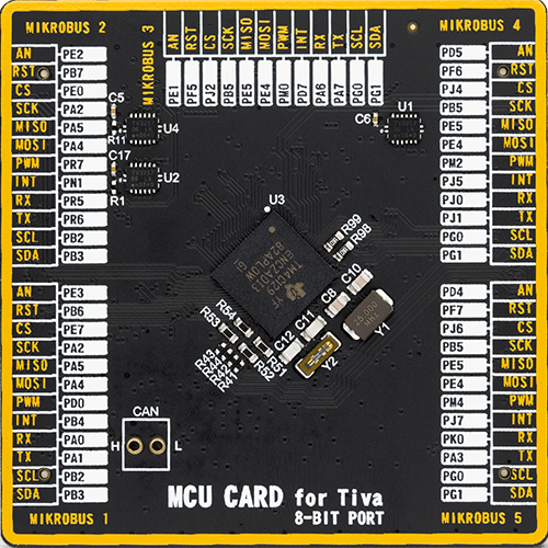
Type
8th Generation
Architecture
ARM Cortex-M4
MCU Memory (KB)
1024
Silicon Vendor
Texas Instruments
Pin count
212
RAM (Bytes)
262144
You complete me!
Accessories
The 28BYJ-48 is an adaptable 5VDC stepper motor with a compact design, ideal for various applications. It features four phases, a speed variation ratio of 1/64, and a stride angle of 5.625°/64 steps, allowing precise control. The motor operates at a frequency of 100Hz and has a DC resistance of 50Ω ±7% at 25°C. It boasts an idle in-traction frequency greater than 600Hz and an idle out-traction frequency exceeding 1000Hz, ensuring reliability in different scenarios. With a self-positioning torque and in-traction torque both exceeding 34.3mN.m at 120Hz, the 28BYJ-48 offers robust performance. Its friction torque ranges from 600 to 1200 gf.cm, while the pull-in torque is 300 gf.cm. This motor makes a reliable and efficient choice for your stepper motor needs.

Used MCU Pins
mikroBUS™ mapper
Take a closer look
Click board™ Schematic

Step by step
Project assembly

Start by selecting your development board and Click board™. Begin with the Fusion for Tiva v8 as your development board.


Track your results in real time
Application Output
1. Application Output - In Debug mode, the 'Application Output' window enables real-time data monitoring, offering direct insight into execution results. Ensure proper data display by configuring the environment correctly using the provided tutorial.

2. UART Terminal - Use the UART Terminal to monitor data transmission via a USB to UART converter, allowing direct communication between the Click board™ and your development system. Configure the baud rate and other serial settings according to your project's requirements to ensure proper functionality. For step-by-step setup instructions, refer to the provided tutorial.

3. Plot Output - The Plot feature offers a powerful way to visualize real-time sensor data, enabling trend analysis, debugging, and comparison of multiple data points. To set it up correctly, follow the provided tutorial, which includes a step-by-step example of using the Plot feature to display Click board™ readings. To use the Plot feature in your code, use the function: plot(*insert_graph_name*, variable_name);. This is a general format, and it is up to the user to replace 'insert_graph_name' with the actual graph name and 'variable_name' with the parameter to be displayed.

Software Support
Library Description
This library contains API for STSPIN220 Click driver.
Key functions:
stspin220_set_direction- This function sets the motor direction by setting the DIR pin logic statestspin220_drive_motor- This function drives the motor for the specific number of steps at the selected speedstspin220_reset_device- This function resets the device by toggling the RST pin
Open Source
Code example
The complete application code and a ready-to-use project are available through the NECTO Studio Package Manager for direct installation in the NECTO Studio. The application code can also be found on the MIKROE GitHub account.
/*!
 * @file main.c
 * @brief STSPIN220 Click Example.
 *
 * # Description
 * This example demonstrates the use of the STSPIN220 Click board by driving the
 * motor in both directions for a desired number of steps.
 *
 * The demo application is composed of two sections :
 *
 * ## Application Init
 * Initializes the driver and performs the Click default configuration.
 *
 * ## Application Task
 * Drives the motor clockwise for 200 steps and then counter-clockwise with a 2 seconds
 * delay delay on driving mode change. All data is being logged on the USB UART where
 * you can track the program flow.
 *
 * @author Stefan Filipovic
 *
 */

#include "board.h"
#include "log.h"
#include "stspin220.h"

static stspin220_t stspin220;   /**< STSPIN220 Click driver object. */
static log_t logger;    /**< Logger object. */

void application_init ( void )
{
    log_cfg_t log_cfg;  /**< Logger config object. */
    stspin220_cfg_t stspin220_cfg;  /**< Click config object. */

    /**
     * Logger initialization.
     * Default baud rate: 115200
     * Default log level: LOG_LEVEL_DEBUG
     * @note If USB_UART_RX and USB_UART_TX
     * are defined as HAL_PIN_NC, you will
     * need to define them manually for log to work.
     * See @b LOG_MAP_USB_UART macro definition for detailed explanation.
     */
    LOG_MAP_USB_UART( log_cfg );
    log_init( &logger, &log_cfg );
    log_info( &logger, " Application Init " );

    // Click initialization.
    stspin220_cfg_setup( &stspin220_cfg );
    STSPIN220_MAP_MIKROBUS( stspin220_cfg, MIKROBUS_1 );
    if ( DIGITAL_OUT_UNSUPPORTED_PIN == stspin220_init( &stspin220, &stspin220_cfg ) )
    {
        log_error( &logger, " Communication init." );
        for ( ; ; );
    }

    stspin220_default_cfg ( &stspin220 );

    log_info( &logger, " Application Task " );
}

void application_task ( void )
{
    log_printf ( &logger, " Move 200 steps clockwise, speed: slow\r\n\n" );
    stspin220_set_direction ( &stspin220, STSPIN220_DIR_CW );
    stspin220_drive_motor ( &stspin220, 200, STSPIN220_SPEED_SLOW );
    Delay_ms ( 1000 );
    Delay_ms ( 1000 );

    log_printf ( &logger, " Move 200 steps counter-clockwise, speed: fast\r\n\n" );
    stspin220_set_direction ( &stspin220, STSPIN220_DIR_CCW );
    stspin220_drive_motor ( &stspin220, 200, STSPIN220_SPEED_FAST );
    Delay_ms ( 1000 );
    Delay_ms ( 1000 );
}

int main ( void )
{
    /* Do not remove this line or clock might not be set correctly. */
    #ifdef PREINIT_SUPPORTED
    preinit();
    #endif

    application_init( );

    for ( ; ; )
    {
        application_task( );
    }

    return 0;
}

// ------------------------------------------------------------------------ END


