Maximize motor performance with TB6549FG and PIC32MX795F512L
Unleash the motor's full potential

Published Jun 08, 2023
Click board™
DC MOTOR 3 Click
Dev. board
UNI-DS v8
Compiler
NECTO Studio
MCU
PIC32MX795F512L
Take control of your motors and drive innovation in your engineering design with brushed motor control of up to 2 Amps!
A
A
Hardware Overview
How does it work?
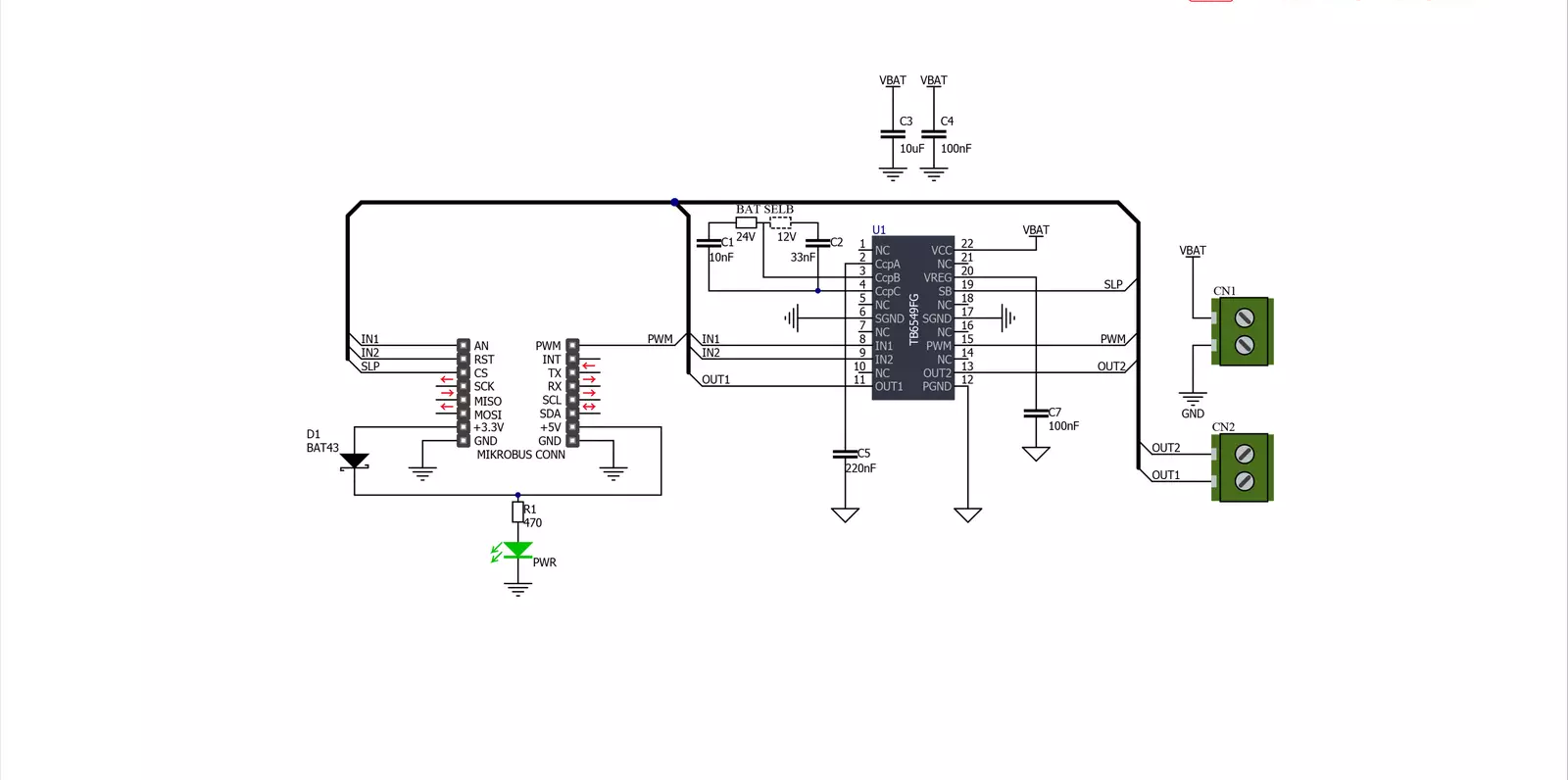
DC MOTOR 3 Click is based on the TB6549FG, a full-bridge driver for direct current motors from Toshiba Semiconductor. The TB6549FG has built-in overcurrent protection, a thermal shutdown circuit, a standby system, and PWM motor capability. Full-bridge means it can run the connected motor in both directions. It has four modes to control the DC motors, CW, CCW, short brake, and stop. To prevent a penetrating current when upper and lower transistors are ON, a dead time of 300ns is provided in the IC when either of the transistors changes from ON to OFF, or vice versa. Note that a dead time is also provided in the IC at the time of transition between CW and CCW or between CW (CCW) and short brake mode, thereby eliminating the need for an OFF time. The TB6549FG also integrates an efficient full bridge
with low ON resistance of approximately 1Ω. Motor speed on this Click board™ can be controlled by PWM signal the mikroBUS™ socket. When PWM control is provided, normal and short brake operations are repeated. Do not attempt to control the output by inputting PWM signals to the standby pin. Doing so may cause the output signal to become unstable, destroying the IC. In standby mode, all circuits are turned OFF except the standby circuit and the charge pump circuit under the standby condition. DC MOTOR 3 Click features the SLP pin to control the standby mode. Pins IN1 and IN2 can select one of four driving modes, CW, CCW, short brake, and stop, by setting the logic states according to the table in the datasheet. DC MOTOR 3 Click does not use the power for the TB6549FG or the connected motor from the
mikroBUS™ socket. The right screw terminal powers the motor with a maximum supply voltage of 27V. The DC motor can be connected over the left screw terminal depending on the desired direction of the motor drive with a 2A max of output. At the bottom of the DC MOTOR 3 Click is a BAT SEL jumper to set the charge pump for driving the gate for the upper power transistor in the output circuit. On this Click board™, 24V is selected by default. This Click board™ can operate with either 3.3V or 5V logic voltage levels. This way, both 3.3V and 5V capable MCUs can use the communication lines properly. However, the Click board™ comes equipped with a library containing easy-to-use functions and an example code that can be used, as a reference, for further development.

Features overview
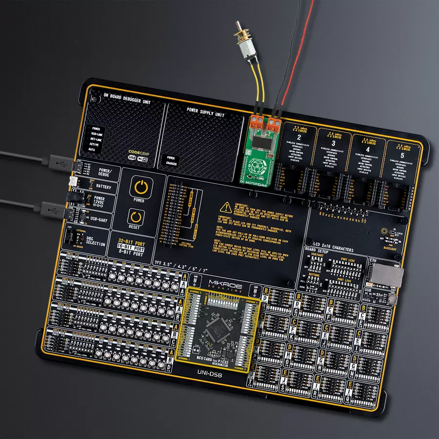
Development board
UNI-DS v8 is a development board specially designed for the needs of rapid development of embedded applications. It supports a wide range of microcontrollers, such as different STM32, Kinetis, TIVA, CEC, MSP, PIC, dsPIC, PIC32, and AVR MCUs regardless of their number of pins, and a broad set of unique functions, such as the first-ever embedded debugger/programmer over WiFi. The development board is well organized and designed so that the end-user has all the necessary elements, such as switches, buttons, indicators, connectors, and others, in one place. Thanks to innovative manufacturing technology, UNI-DS v8 provides a fluid and immersive working experience, allowing access anywhere and under any
circumstances at any time. Each part of the UNI-DS v8 development board contains the components necessary for the most efficient operation of the same board. An advanced integrated CODEGRIP programmer/debugger module offers many valuable programming/debugging options, including support for JTAG, SWD, and SWO Trace (Single Wire Output)), and seamless integration with the Mikroe software environment. Besides, it also includes a clean and regulated power supply module for the development board. It can use a wide range of external power sources, including a battery, an external 12V power supply, and a power source via the USB Type-C (USB-C) connector. Communication options such as USB-UART, USB
HOST/DEVICE, CAN (on the MCU card, if supported), and Ethernet is also included. In addition, it also has the well-established mikroBUS™ standard, a standardized socket for the MCU card (SiBRAIN standard), and two display options for the TFT board line of products and character-based LCD. UNI-DS v8 is an integral part of the Mikroe ecosystem for rapid development. Natively supported by Mikroe software tools, it covers many aspects of prototyping and development thanks to a considerable number of different Click boards™ (over a thousand boards), the number of which is growing every day.

Microcontroller Overview
MCU Card / MCU
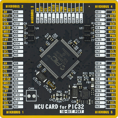
Type
8th Generation
Architecture
PIC32
MCU Memory (KB)
512
Silicon Vendor
Microchip
Pin count
100
RAM (Bytes)
131072
You complete me!
Accessories
DC Gear Motor - 430RPM (3-6V) represents an all-in-one combination of a motor and gearbox, where the addition of gear leads to a reduction of motor speed while increasing the torque output. This gear motor has a spur gearbox, making it a highly reliable solution for applications with lower torque and speed requirements. The most critical parameters for gear motors are speed, torque, and efficiency, which are, in this case, 520RPM with no load and 430RPM at maximum efficiency, alongside a current of 60mA and a torque of 50g.cm. Rated for a 3-6V operational voltage range and clockwise/counterclockwise rotation direction, this motor represents an excellent solution for many functions initially performed by brushed DC motors in robotics, medical equipment, electric door locks, and much more.

Used MCU Pins
mikroBUS™ mapper
Take a closer look
Click board™ Schematic
Step by step
Project assembly

Start by selecting your development board and Click board™. Begin with the UNI-DS v8 as your development board.


Software Support
Library Description
This library contains API for DC MOTOR 3 Click driver.
Key functions:
dcmotor3_clockwise- This function set the direction of rotation in the clockwise direction by sets AN pin and clear RST pin.dcmotor3_counter_clockwise- This function set the direction of rotation in the counter clockwise direction by clear AN pin and sets RST pin.dcmotor3_short_brake- This function brake the engine by sets AN and RST pins on DC Motor 3 Click board.
Open Source
Code example
The complete application code and a ready-to-use project are available through the NECTO Studio Package Manager for direct installation in the NECTO Studio. The application code can also be found on the MIKROE GitHub account.
/*!
 * @file
 * @brief DcMotor3 Click example
 *
 * # Description
 * This Click has four operating modes: clockwise, counter-clockwise, short brake and stop.
 * The operating mode is configured through IN1 and IN2 pins.
 *
 * The demo application is composed of two sections :
 *
 * ## Application Init
 * Initialization driver enable's - GPIO,
 * PWM initialization, set PWM duty cycle and PWM frequency, start PWM, enable the engine, and start write log.
 *
 * ## Application Task
 * This is a example which demonstrates the use of DC Motor 3 Click board.
 * DC Motor 3 Click communicates with register via PWM interface.
 * It shows moving in the left direction from slow to fast speed
 * and from fast to slow speed.
 * Results are being sent to the Usart Terminal where you can track their changes.
 *
 *
 * @author Nikola Peric
 *
 */
// ------------------------------------------------------------------- INCLUDES

#include "board.h"
#include "log.h"
#include "dcmotor3.h"

// ------------------------------------------------------------------ VARIABLES

static dcmotor3_t dcmotor3;
static log_t logger;
uint8_t dcmotor3_direction = 1;

// ------------------------------------------------------ APPLICATION FUNCTIONS

void application_init ( void )
{
    log_cfg_t log_cfg;
    dcmotor3_cfg_t cfg;

    /**
     * Logger initialization.
     * Default baud rate: 115200
     * Default log level: LOG_LEVEL_DEBUG
     * @note If USB_UART_RX and USB_UART_TX
     * are defined as HAL_PIN_NC, you will
     * need to define them manually for log to work.
     * See @b LOG_MAP_USB_UART macro definition for detailed explanation.
     */
    LOG_MAP_USB_UART( log_cfg );
    log_init( &logger, &log_cfg );
    log_info( &logger, "---- Application Init ----" );

    //  Click initialization.

    dcmotor3_cfg_setup( &cfg );
    DCMOTOR3_MAP_MIKROBUS( cfg, MIKROBUS_1 );
    dcmotor3_init( &dcmotor3, &cfg );

    dcmotor3_set_duty_cycle ( &dcmotor3, 0.0 );
    dcmotor3_pwm_start( &dcmotor3 );
    Delay_ms ( 1000 );
    dcmotor3_enable( &dcmotor3 );
    Delay_ms ( 1000 );
    log_info( &logger, "---- Application Task ----" );
}

void application_task ( void )
{
    static int8_t duty_cnt = 1;
    static int8_t duty_inc = 1;
    float duty = duty_cnt / 10.0;

    if ( dcmotor3_direction == 1 )
    {
        dcmotor3_clockwise( &dcmotor3 );
        log_printf( &logger, ">>>> CLOCKWISE " );
        dcmotor3_enable ( &dcmotor3 );
    }
    else
    {
        dcmotor3_counter_clockwise( &dcmotor3 );
        log_printf( &logger, "<<<< COUNTER CLOCKWISE " );
        dcmotor3_enable ( &dcmotor3 );
    }

    dcmotor3_set_duty_cycle ( &dcmotor3, duty );
    log_printf( &logger, "Duty: %d%%\r\n", ( uint16_t )( duty_cnt * 10 ) );
    Delay_ms ( 500 );

    if ( 10 == duty_cnt )
    {
        duty_inc = -1;
    }
    else if ( 0 == duty_cnt )
    {
        duty_inc = 1;

        if ( dcmotor3_direction == 1 )
        {
            dcmotor3_direction = 0;
        }
        else if ( dcmotor3_direction == 0 )
        {
            dcmotor3_direction = 1;
        }
    }
    duty_cnt += duty_inc;
}

int main ( void )
{
    /* Do not remove this line or clock might not be set correctly. */
    #ifdef PREINIT_SUPPORTED
    preinit();
    #endif

    application_init( );

    for ( ; ; )
    {
        application_task( );
    }

    return 0;
}

// ------------------------------------------------------------------------ END


