Upgrade your I/O control with TCA6424A and MSP432P401R
From limited to limitless

Published Sep 23, 2023
Click board™
EXPAND 5 Click
Dev. board
Fusion for Tiva v8
Compiler
NECTO Studio
MCU
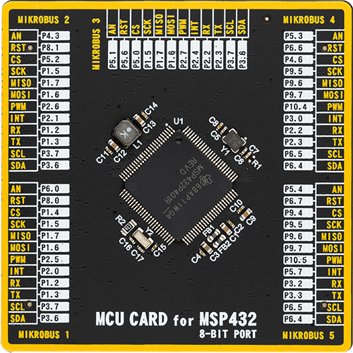
MSP432P401R
Our port expander solution simplifies and amplifies your I/O capabilities, enabling seamless expansion of pins for diverse applications, from automation and IoT to robotics and prototyping
A
A
Hardware Overview
How does it work?
EXPAND 5 Click is based on the TCA6424A, low-voltage 24-bit I2C, and SMBus I/O expander from Texas Instruments. This 24-bit I/O expander for the two-line bidirectional bus is designed to provide general-purpose remote I/O expansion for most microcontroller families via the 400-kHz fast I2C bus. This Click board™ features on-board I2C address jumpers, pull-up resistors, power supply bypass capacitor, and power LED. It operates over a flexible power supply voltage range of 1.65V to 5.5V, which makes it suitable for 3.3V and 5V microcontrollers. At power-on, the I/O pins are configured as inputs. However, the microcontroller can enable the I/Os as either inputs or outputs by writing to the I/O configuration bits. The data for each input or output is kept in the corresponding input or output register. The polarity of the Input Port register can be inverted with the Polarity Inversion register. The microcontroller can reset the TCA6424A in the event of a timeout or other
improper operation by asserting a low in the RESET input. The power-on reset puts the registers in their default state and initializes the I2C interface. The RESET pin causes the same reset/initialization to occur without depowering the part. This Click board™ also has an open-drain interrupt (INT) output that is activated when any input state differs from its corresponding Input Port register state and is used to indicate to the microcontroller that an input state has changed. By sending an interrupt signal on this line, the remote I/O can inform the microcontroller if there is incoming data on its ports without having to communicate via the I2C bus. Thus, the TCA6424A can remain a simple slave device. The TCA6424A communicates with MCU using the standard I2C 2-wire interface. The TCA6424A can respond to one of two 7-bit I2C Bus Slave addresses. The first 6 bits (MSBs) have been factory programmed to 010001. The address pin, ADDR (Pin 26) is
programmed by the user and determines the LSB of the slave address and it can be selected by onboard SMD jumper labeled as ADDR SEL allowing selection of the slave address LSB. The last bit of the slave address defines the operation (read or write) to be performed. A high (1) selects a read operation, while a low (0) selects a write operation. This Click board™ can be supplied and interfaced with both 3.3V and 5V without the need for any external components. The onboard SMD jumper labeled as VCC SEL allows voltage selection for interfacing with both 3.3V and 5V microcontrollers. More information about the TCA6424A can be found in the attached datasheet. However, this Click board™ comes equipped with a library that contains easy to use functions and a usage example that may be used as a reference for the development.


Features overview
Development board
Fusion for TIVA v8 is a development board specially designed for the needs of rapid development of embedded applications. It supports a wide range of microcontrollers, such as different 32-bit ARM® Cortex®-M based MCUs from Texas Instruments, regardless of their number of pins, and a broad set of unique functions, such as the first-ever embedded debugger/programmer over a WiFi network. The development board is well organized and designed so that the end-user has all the necessary elements, such as switches, buttons, indicators, connectors, and others, in one place. Thanks to innovative manufacturing technology, Fusion for TIVA v8 provides a fluid and immersive working experience, allowing access
anywhere and under any circumstances at any time. Each part of the Fusion for TIVA v8 development board contains the components necessary for the most efficient operation of the same board. An advanced integrated CODEGRIP programmer/debugger module offers many valuable programming/debugging options, including support for JTAG, SWD, and SWO Trace (Single Wire Output)), and seamless integration with the Mikroe software environment. Besides, it also includes a clean and regulated power supply module for the development board. It can use a wide range of external power sources, including a battery, an external 12V power supply, and a power source via the USB Type-C (USB-C) connector.
Communication options such as USB-UART, USB HOST/DEVICE, CAN (on the MCU card, if supported), and Ethernet is also included. In addition, it also has the well-established mikroBUS™ standard, a standardized socket for the MCU card (SiBRAIN standard), and two display options for the TFT board line of products and character-based LCD. Fusion for TIVA v8 is an integral part of the Mikroe ecosystem for rapid development. Natively supported by Mikroe software tools, it covers many aspects of prototyping and development thanks to a considerable number of different Click boards™ (over a thousand boards), the number of which is growing every day.

Microcontroller Overview
MCU Card / MCU
Type
8th Generation
Architecture
ARM Cortex-M4
MCU Memory (KB)
256
Silicon Vendor
Texas Instruments
Pin count
100
RAM (Bytes)
65536
Used MCU Pins
mikroBUS™ mapper
Take a closer look
Click board™ Schematic

Step by step
Project assembly

Start by selecting your development board and Click board™. Begin with the Fusion for Tiva v8 as your development board.


Software Support
Library Description
This library contains API for EXPAND 5 Click driver.
Key functions:
expand5_write_all_banks- Set all OUTPUT pins' logic levels in all banks functionexpand5_get_bank_pol- Get all pin polarity ( normal/inverted ) settings from one bank functionexpand5_get_pin_dir- Get a single pin's direction ( I/O ) setting function
Open Source
Code example
The complete application code and a ready-to-use project are available through the NECTO Studio Package Manager for direct installation in the NECTO Studio. The application code can also be found on the MIKROE GitHub account.
/*!
 * \file
 * \brief Expand5 Click example
 *
 * # Description
 * This example demonstrates the use of Expand 5 Click board.
 *
 * The demo application is composed of two sections :
 *
 * ## Application Init
 * Initalizes I2C driver, resets the device, configures all pins as output and makes an initial log.
 *
 * ## Application Task
 * This example shows the capabilities of the EXPAND 5 Click by toggling each of the 24 available pins.
 *
 * \author MikroE Team
 *
 */
// ------------------------------------------------------------------- INCLUDES

#include "board.h"
#include "log.h"
#include "expand5.h"

// ------------------------------------------------------------------ VARIABLES

static expand5_t expand5;
static log_t logger;

uint8_t pin_num;
uint8_t bank_out = 0x00;
uint8_t bank_low = 0x00;
char log_txt[ 50 ];

// ------------------------------------------------------ APPLICATION FUNCTIONS

void application_init ( void )
{
    log_cfg_t log_cfg;
    expand5_cfg_t cfg;

    /**
     * Logger initialization.
     * Default baud rate: 115200
     * Default log level: LOG_LEVEL_DEBUG
     * @note If USB_UART_RX and USB_UART_TX
     * are defined as HAL_PIN_NC, you will
     * need to define them manually for log to work.
     * See @b LOG_MAP_USB_UART macro definition for detailed explanation.
     */
    LOG_MAP_USB_UART( log_cfg );
    log_init( &logger, &log_cfg );
    log_info( &logger, "---- Application Init ----" );

    //  Click initialization.

    expand5_cfg_setup( &cfg );
    EXPAND5_MAP_MIKROBUS( cfg, MIKROBUS_1 );
    expand5_init( &expand5, &cfg );

    Delay_ms ( 100 );

    log_printf( &logger, "------------------- \r\n" );
    log_printf( &logger, "   EXPAND 5 Click   \r\n" );
    log_printf( &logger, "------------------- \r\n" );
    expand5_reset( &expand5 );
    expand5_set_all_dir( &expand5, bank_out, bank_out, bank_out );
    Delay_ms ( 100 );
    log_printf( &logger, "  Pins configured   \r\n" );
    log_printf( &logger, "     as output      \r\n" );
    log_printf( &logger, "------------------- \r\n" );
}

void application_task ( void )
{
    for ( pin_num = EXPAND5_P00; pin_num <= EXPAND5_P27; pin_num++ )
    {
        expand5_write_all_banks ( &expand5, bank_low, bank_low, bank_low );
        expand5_write_pin ( &expand5, pin_num, EXPAND5_HIGH );
        log_printf( &logger, "Pin %u is high \r\n", ( uint16_t ) pin_num );

        Delay_ms ( 200 );
        expand5_write_all_banks ( &expand5, bank_low, bank_low, bank_low );
    }
    log_printf( &logger, "------------------- \r\n" );
    Delay_ms ( 1000 );
}

int main ( void )
{
    /* Do not remove this line or clock might not be set correctly. */
    #ifdef PREINIT_SUPPORTED
    preinit();
    #endif

    application_init( );

    for ( ; ; )
    {
        application_task( );
    }

    return 0;
}

// ------------------------------------------------------------------------ END
Additional Support
Resources
Category:Port expander


