Get ready for unparalleled speed and data capacity thanks to TCAN1462 and STM32L496AG
Experience the best of both worlds: CAN for stability, CAN FD for speed
Published Jul 22, 2025
Click board™
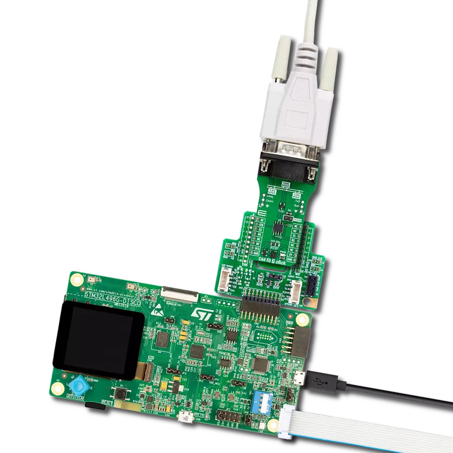
CAN FD 7 Click
Dev. board
Discovery kit with STM32L496AG MCU
Compiler
NECTO Studio
MCU
STM32L496AG
Empower your network with a CAN transceiver that adapts to the demands of today's dynamic environments. Our solution effortlessly bridges the worlds of CAN and CAN FD, offering you the flexibility and speed you need for your evolving applications.
A
A
Hardware Overview
How does it work?
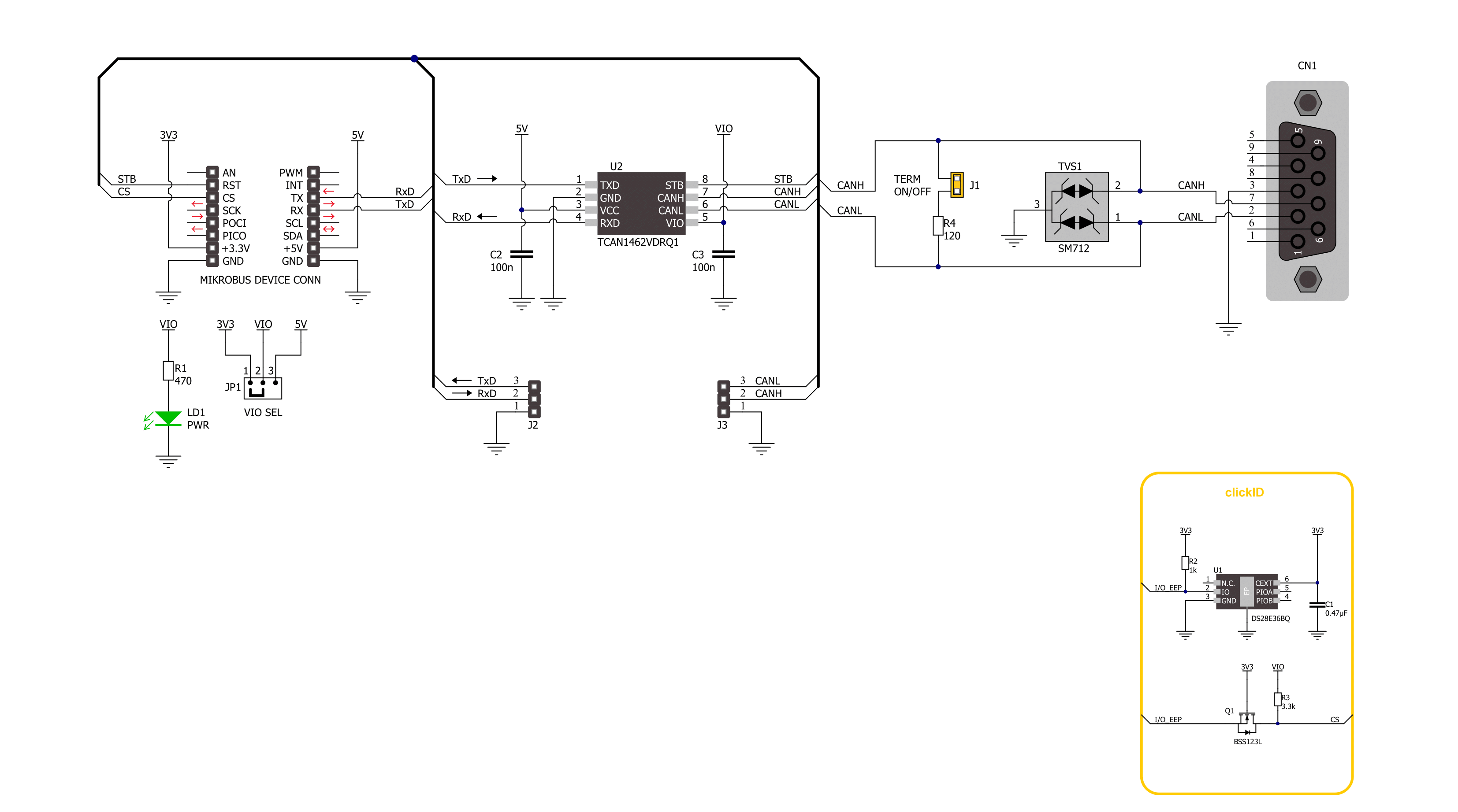
CAN FD 7 Click is based on the TCAN1462, an automotive fault-protected CAN FD transceiver from Texas Instruments. The transceiver is data rate agnostic, making it backward compatible for supporting classical CAN applications while also supporting CAN FD networks up to 8 Mbps. It actively improves the bus signal by reducing ringing effects in complex topologies, enabling higher throughput. In addition, the transceiver has a much tighter bit of timing symmetry, which provides a larger timing window to sample the correct bit and enables error-free communication in large complex star networks where ringing and bit distortion are inherent. It also has a passive behavior when unpowered and supports a hot plug, with power up or down glitch-free
operation. As for protection, the transceiver features IEC ESD protection, under-voltage, thermal shutdown, TXD dominant state timeout, and more. This Click board™ comes equipped with the industry-standard DE-9 connector, making interfacing with the CAN bus simple and easy. Besides, the user can connect the CAN signals directly through the CAN External header located on the board's left edge (unpopulated by default). The same goes for the UART signals over the TXD/RXD header. The termination 120Ω resistor labeled TERM allows CAN termination to the bus, which you can disable. CAN FD 7 Click uses a standard UART interface to communicate with the host MCU with commonly used UART RX and TX pins. Besides the normal mode, the transceiver
has standby mode support, which puts the transceiver in ultra-low current consumption mode, which, upon receiving a valid wake-up pattern (WUP) on the CAN bus, signals to the microcontroller through the RXD pin. The MCU can then put the device into normal mode using the standby mode STB input pin. This Click board™ can operate with either 3.3V or 5V logic voltage levels selected via the VIO SEL jumper. This way, both 3.3V and 5V capable MCUs can use the communication lines properly. Also, this Click board™ comes equipped with a library containing easy-to-use functions and an example code that can be used as a reference for further development.

Features overview
Development board
The 32L496GDISCOVERY Discovery kit serves as a comprehensive demonstration and development platform for the STM32L496AG microcontroller, featuring an Arm® Cortex®-M4 core. Designed for applications that demand a balance of high performance, advanced graphics, and ultra-low power consumption, this kit enables seamless prototyping for a wide range of embedded solutions. With its innovative energy-efficient
architecture, the STM32L496AG integrates extended RAM and the Chrom-ART Accelerator, enhancing graphics performance while maintaining low power consumption. This makes the kit particularly well-suited for applications involving audio processing, graphical user interfaces, and real-time data acquisition, where energy efficiency is a key requirement. For ease of development, the board includes an onboard ST-LINK/V2-1
debugger/programmer, providing a seamless out-of-the-box experience for loading, debugging, and testing applications without requiring additional hardware. The combination of low power features, enhanced memory capabilities, and built-in debugging tools makes the 32L496GDISCOVERY kit an ideal choice for prototyping advanced embedded systems with state-of-the-art energy efficiency.

Microcontroller Overview
MCU Card / MCU

Architecture
ARM Cortex-M4
MCU Memory (KB)
1024
Silicon Vendor
STMicroelectronics
Pin count
169
RAM (Bytes)
327680
You complete me!
Accessories
DB9 Cable Female-to-Female (2m) cable is essential for establishing dependable serial data connections between devices. With its DB9 female connectors on both ends, this cable enables a seamless link between various equipment, such as computers, routers, switches, and other serial devices. Measuring 2 meters in length, it offers flexibility in arranging your setup without compromising data transmission quality. Crafted with precision, this cable ensures consistent and reliable data exchange, making it suitable for industrial applications, office environments, and home setups. Whether configuring networking equipment, accessing console ports, or utilizing serial peripherals, this cable's durable construction and robust connectors guarantee a stable connection. Simplify your data communication needs with the 2m DB9 female-to-female cable, an efficient solution designed to meet your serial connectivity requirements easily and efficiently.

Used MCU Pins
mikroBUS™ mapper
Take a closer look
Click board™ Schematic
Step by step
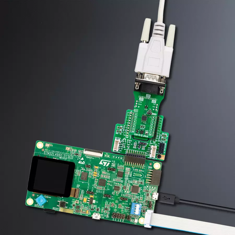
Project assembly

Start by selecting your development board and Click board™. Begin with the Discovery kit with STM32L496AG MCU as your development board.


Software Support
Library Description
This library contains API for CAN FD 7 Click driver.
Key functions:
canfd7_generic_write- CAN FD 7 data writing function.canfd7_generic_read- CAN FD 7 data reading function.canfd7_set_stb_pin- CAN FD 7 set STB pin function.
Open Source
Code example
The complete application code and a ready-to-use project are available through the NECTO Studio Package Manager for direct installation in the NECTO Studio. The application code can also be found on the MIKROE GitHub account.
/*!
 * @file main.c
 * @brief CAN FD 7 Click Example.
 *
 * # Description
 * This example writes and reads and processes data from CAN FD 7 Click.
 * The library also includes a function for selection of the output polarity.
 *
 * The demo application is composed of two sections :
 *
 * ## Application Init
 * Initializes the driver and performs the Click default configuration.
 *
 * ## Application Task
 * This example contains Transmitter/Receiver task depending on uncommented code.
 * Receiver logs each received byte to the UART for data logging,
 * while the transmitter sends messages every 2 seconds.
 *
 * ## Additional Function
 * - static err_t canfd7_process ( canfd7_t *ctx )
 *
 * @author Stefan Ilic
 *
 */

#include "board.h"
#include "log.h"
#include "canfd7.h"

#define PROCESS_BUFFER_SIZE 200
#define TX_MESSAGE "CAN FD 7 Click \r\n"

// Comment out the line below in order to switch the application mode to receiver.
#define DEMO_APP_TRANSMITTER

static canfd7_t canfd7;
static log_t logger;

static uint8_t app_buf[ PROCESS_BUFFER_SIZE ] = { 0 };
static int32_t app_buf_len = 0;

/**
 * @brief CAN FD 7 data reading function.
 * @details This function reads data from device and concatenates data to application buffer.
 * @param[in] ctx : Click context object.
 * See #canfd7_t object definition for detailed explanation.
 * @return @li @c  0 - Read some data.
 *         @li @c -1 - Nothing is read.
 * See #err_t definition for detailed explanation.
 * @note None.
 */
static err_t canfd7_process ( canfd7_t *ctx );

void application_init ( void )
{
    log_cfg_t log_cfg;  /**< Logger config object. */
    canfd7_cfg_t canfd7_cfg;  /**< Click config object. */

    /**
     * Logger initialization.
     * Default baud rate: 115200
     * Default log level: LOG_LEVEL_DEBUG
     * @note If USB_UART_RX and USB_UART_TX
     * are defined as HAL_PIN_NC, you will
     * need to define them manually for log to work.
     * See @b LOG_MAP_USB_UART macro definition for detailed explanation.
     */
    LOG_MAP_USB_UART( log_cfg );
    log_init( &logger, &log_cfg );
    log_info( &logger, " Application Init " );

    // Click initialization.
    canfd7_cfg_setup( &canfd7_cfg );
    CANFD7_MAP_MIKROBUS( canfd7_cfg, MIKROBUS_1 );
    if ( UART_ERROR == canfd7_init( &canfd7, &canfd7_cfg ) )
    {
        log_error( &logger, " Communication init." );
        for ( ; ; );
    }

    canfd7_default_cfg ( &canfd7 );

#ifdef DEMO_APP_TRANSMITTER
    log_info( &logger, "---- Transmitter mode ----" );
#else
    log_info( &logger, "---- Receiver mode ----" );
#endif

    log_info( &logger, " Application Task " );
}

void application_task ( void )
{
#ifdef DEMO_APP_TRANSMITTER
    canfd7_generic_write( &canfd7, TX_MESSAGE, strlen( TX_MESSAGE ) );
    log_info( &logger, "---- Data sent ----" );
    Delay_ms ( 1000 );
    Delay_ms ( 1000 );
#else
    canfd7_process( &canfd7 );
#endif
}

int main ( void )
{
    /* Do not remove this line or clock might not be set correctly. */
    #ifdef PREINIT_SUPPORTED
    preinit();
    #endif

    application_init( );

    for ( ; ; )
    {
        application_task( );
    }

    return 0;
}

static err_t canfd7_process ( canfd7_t *ctx )
{
    uint32_t rx_size;
    char rx_buf[ PROCESS_BUFFER_SIZE ] = { 0 };
    rx_size = canfd7_generic_read( &canfd7, rx_buf, PROCESS_BUFFER_SIZE );
    if ( rx_size > 0 )
    {
        log_printf( &logger, "%s", rx_buf );
        return CANFD7_OK;
    }
    return CANFD7_ERROR;
}

// ------------------------------------------------------------------------ END
Additional Support
Resources
Category:CAN


