Experience ultra-fast CAN connectivity with TCAN4550 and TM4C129ENCPDT
Lightning-fast communication
Published Aug 06, 2023
Click board™
CAN FD 6 Click
Dev. board
Fusion for Tiva v8
Compiler
NECTO Studio
MCU
TM4C129ENCPDT
Engineered for high-speed excellence, our CAN FD transceiver delivers unmatched performance in automotive and industrial systems
A
A
Hardware Overview
How does it work?
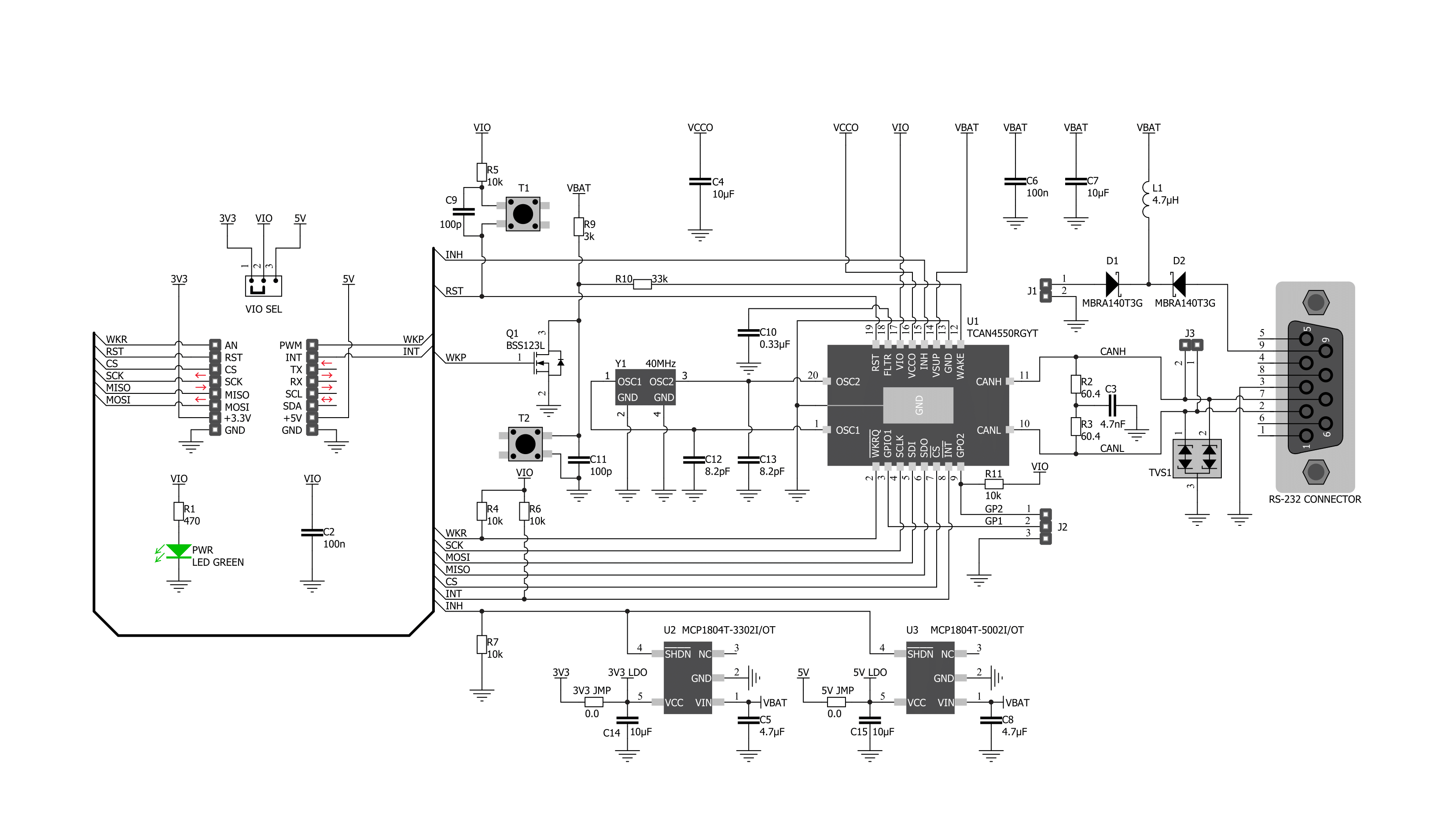
CAN FD 6 Click is based on the TCAN4550, a CAN transceiver that supports CAN and CAN FD protocols and provides an interface between the CAN bus and the CAN protocol controller up to 5 megabits per second (Mbps) from Texas Instruments. It is characterized by high-bandwidth and data-rate flexibility, provides an SPI interface between the CAN bus and the system processor, and supports wake-up features local and bus wake using the CAN bus. The device includes many protection features providing CAN bus robustness, including fail-safe mode, internal dominant state timeout, and wide bus operating range. The TCAN4550 has one pin for waking the device from Sleep mode. This pin is connected to an external button labeled WAKE and the PWM pin of the mikroBUS™ socket labeled WKP to generate a local Wake-Up function. A Wake-Up event on the CAN bus switches the inhibit output pin INH to the high level. The INH pin provides an internal switch towards the battery supply voltage and controls external voltage regulators, the MCP1804 from
Microchip. Through SMD jumpers labeled as 3V3JMP and 5VJMP, the LDO's output voltages can power up the mikroBUS™ 3.3V and 5V power rails. However, it should be noted that Mikroe does not advise powering up their systems this way. That is why these jumpers are left unpopulated by default. CAN FD 6 Click communicates with MCU using a standard SPI interface supporting clock rates up to 18MHz to transmit and reception CAN frames. With an additional 40MHz crystal, the TCAN4550 can meet CAN FD rates up to 5 Mbps data rates to support higher data throughput and operates from a 6V to 24V external power supply header on the board's right side. This feature makes the TCAN4550 device ideal for many applications, including automotive ones. This Click board™ comes equipped with the industry-standard DB-9 connector, making interfacing with the CAN bus simple and easy. Besides, the user can connect the CAN signals directly through the CAN External header on the board's left edge. In addition to these features, the TCAN4550 uses
several GPIO pins connected to the mikroBUS™ socket. The RST pin, the mikroBUS™, can perform the Hardware Reset function, which resets the device to the default settings and puts it into standby mode. This feature can also be achieved through the onboard push-button labeled as RST. Next to these pins, the ATA6571 uses the WKR pin as a dedicated wake-up request pin from a bus wake request and the INT pin as an interrupt feature routed on the AN and INT pin of the mikroBUS™ socket. The user can also use GPIO pins from the header on the board's right side for interrupt purposes. This Click board™ can operate with both 3.3V and 5V logic voltage levels selected via the VIO SEL jumper. It allows both 3.3V and 5V capable MCUs to use the UART communication lines properly. However, the Click board™ comes equipped with a library containing easy-to-use functions and an example code that can be used, as a reference, for further development.

Features overview
Development board
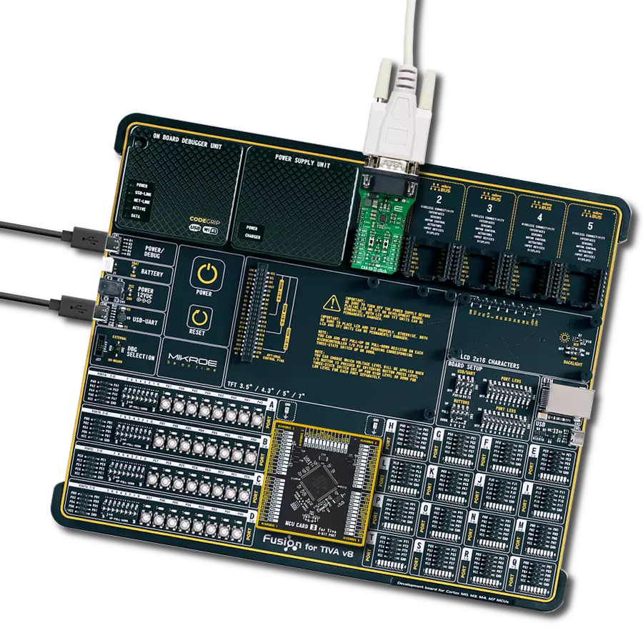
Fusion for TIVA v8 is a development board specially designed for the needs of rapid development of embedded applications. It supports a wide range of microcontrollers, such as different 32-bit ARM® Cortex®-M based MCUs from Texas Instruments, regardless of their number of pins, and a broad set of unique functions, such as the first-ever embedded debugger/programmer over a WiFi network. The development board is well organized and designed so that the end-user has all the necessary elements, such as switches, buttons, indicators, connectors, and others, in one place. Thanks to innovative manufacturing technology, Fusion for TIVA v8 provides a fluid and immersive working experience, allowing access
anywhere and under any circumstances at any time. Each part of the Fusion for TIVA v8 development board contains the components necessary for the most efficient operation of the same board. An advanced integrated CODEGRIP programmer/debugger module offers many valuable programming/debugging options, including support for JTAG, SWD, and SWO Trace (Single Wire Output)), and seamless integration with the Mikroe software environment. Besides, it also includes a clean and regulated power supply module for the development board. It can use a wide range of external power sources, including a battery, an external 12V power supply, and a power source via the USB Type-C (USB-C) connector.
Communication options such as USB-UART, USB HOST/DEVICE, CAN (on the MCU card, if supported), and Ethernet is also included. In addition, it also has the well-established mikroBUS™ standard, a standardized socket for the MCU card (SiBRAIN standard), and two display options for the TFT board line of products and character-based LCD. Fusion for TIVA v8 is an integral part of the Mikroe ecosystem for rapid development. Natively supported by Mikroe software tools, it covers many aspects of prototyping and development thanks to a considerable number of different Click boards™ (over a thousand boards), the number of which is growing every day.

Microcontroller Overview
MCU Card / MCU

Type
8th Generation
Architecture
ARM Cortex-M4
MCU Memory (KB)
1024
Silicon Vendor
Texas Instruments
Pin count
128
RAM (Bytes)
262144
You complete me!
Accessories
DB9 Cable Female-to-Female (2m) cable is essential for establishing dependable serial data connections between devices. With its DB9 female connectors on both ends, this cable enables a seamless link between various equipment, such as computers, routers, switches, and other serial devices. Measuring 2 meters in length, it offers flexibility in arranging your setup without compromising data transmission quality. Crafted with precision, this cable ensures consistent and reliable data exchange, making it suitable for industrial applications, office environments, and home setups. Whether configuring networking equipment, accessing console ports, or utilizing serial peripherals, this cable's durable construction and robust connectors guarantee a stable connection. Simplify your data communication needs with the 2m DB9 female-to-female cable, an efficient solution designed to meet your serial connectivity requirements easily and efficiently.

Used MCU Pins
mikroBUS™ mapper
Take a closer look
Click board™ Schematic
Step by step
Project assembly

Start by selecting your development board and Click board™. Begin with the Fusion for Tiva v8 as your development board.


Software Support
Library Description
This library contains API for CAN FD 6 Click driver.
Key functions:
canfd6_mcan_write_txbuffer- This function will write a CAN message to a specified TX buffer that can be transmitted at a later time with the transmit buffer contents functioncanfd6_mcan_transmit_buffer_contents- This function writes the specified buffer index bit value into the TXBAR register to request a message to sendcanfd6_mcan_read_nextfifo- This function will read the next MCAN FIFO element specified and return the corresponding header information and data payload.
Open Source
Code example
The complete application code and a ready-to-use project are available through the NECTO Studio Package Manager for direct installation in the NECTO Studio. The application code can also be found on the MIKROE GitHub account.
/*!
 * @file main.c
 * @brief CANFD6 Click example
 *
 * # Description
 * This application presents the capabilities of the
 * CAN FD 6 Click board. The board can be used both
 * as a receiver and a transmitter. Use def directive
 * to define the receive or transmit app.
 *
 * The demo application is composed of two sections :
 *
 * ## Application Init
 * The app starts by initializing the UART LOG and
 * SPI drivers. The default cfg function performs the
 * mandatory settings of the device. The user's default
 * configuration can be modified ( for more information
 * about device configuration, check the datasheet ).
 * Additionally, the app writes two messages to the FIFO
 * buffer and sends them if the transmit buffer content
 * event is triggered.
 *
 * ## Application Task
 * Depending on the defined app option, the application
 * task performs the following procedure. If the transmitter
 * is preferred, the application task triggers the transmit
 * buffer contents event of the first message and, later on,
 * the second message. On the other hand, the receiver waits
 * for the CAN FD interrupt, where the payload is read along
 * with the header ID.
 *
 * @author Stefan Nikolic
 *
 */

#include "board.h"
#include "log.h"
#include "canfd6.h"

// Comment out the line below in order to switch the application mode to receiver
#define DEMO_APP_TRANSMITTER

#define CANFD6_FIRST_MSG                        0
#define CANFD6_SECOND_MSG                       1

static canfd6_t canfd6;
static log_t logger;

void application_init ( void ) {
    log_cfg_t log_cfg;        /**< Logger config object. */
    canfd6_cfg_t canfd6_cfg;  /**< Click config object. */

    /**
     * Logger initialization.
     * Default baud rate: 115200
     * Default log level: LOG_LEVEL_DEBUG
     * @note If USB_UART_RX and USB_UART_TX
     * are defined as HAL_PIN_NC, you will
     * need to define them manually for log to work.
     * See @b LOG_MAP_USB_UART macro definition for detailed explanation.
     */
    LOG_MAP_USB_UART( log_cfg );
    log_init( &logger, &log_cfg );
    log_info( &logger, " Application Init " );

    // Click initialization.
    canfd6_cfg_setup( &canfd6_cfg );
    CANFD6_MAP_MIKROBUS( canfd6_cfg, MIKROBUS_1 );
    err_t init_flag = canfd6_init( &canfd6, &canfd6_cfg );
    if ( init_flag == SPI_MASTER_ERROR ) {
        log_error( &logger, " Application Init Error. " );
        log_info( &logger, " Please, run program again... " );

        for ( ; ; );
    }

    canfd6_default_cfg( &canfd6 );
    Delay_ms ( 100 );
#ifdef DEMO_APP_TRANSMITTER
    canfd6_mcan_tx_header_t canfd6_header = { 0 };
    uint8_t data_send_buf[ 64 ] = { 0 };
    strcpy ( data_send_buf, "MIKROE" );
    canfd6_header.DLC = CANFD6_MCAN_DLC_6B;
    canfd6_header.ID = 0x123;
    canfd6_header.FDF = 1;
    canfd6_header.BRS = 1;
    canfd6_header.EFC = 0;
    canfd6_header.MM  = 0;
    canfd6_header.RTR = 0;
    canfd6_header.XTD = 0;
    canfd6_header.ESI = 0;
    canfd6_mcan_write_txbuffer( &canfd6, CANFD6_FIRST_MSG, &canfd6_header, data_send_buf );

    strcpy ( data_send_buf, "CAN FD 6 Click board" );
    canfd6_header.DLC = CANFD6_MCAN_DLC_20B;
    canfd6_header.ID = 0x456;
    canfd6_header.FDF = 1;
    canfd6_header.BRS = 1;
    canfd6_header.EFC = 0;
    canfd6_header.MM  = 0;
    canfd6_header.RTR = 0;
    canfd6_header.XTD = 0;
    canfd6_header.ESI = 0;
    canfd6_mcan_write_txbuffer( &canfd6, CANFD6_SECOND_MSG, &canfd6_header, data_send_buf );
    log_printf( &logger, " Application Mode: Transmitter\r\n" );
#else
    log_printf( &logger, " Application Mode: Receiver\r\n" );
#endif
    log_info( &logger, " Application Task " );
}

void application_task ( void ) {
#ifdef DEMO_APP_TRANSMITTER
    log_printf( &logger, " Transmit first message\r\n" );
    canfd6_mcan_transmit_buffer_contents( &canfd6, CANFD6_FIRST_MSG );
    Delay_ms ( 1000 );
    Delay_ms ( 1000 );
    log_printf( &logger, " Transmit second message\r\n" );
    canfd6_mcan_transmit_buffer_contents( &canfd6, CANFD6_SECOND_MSG );
    Delay_ms ( 1000 );
    Delay_ms ( 1000 );
#else
    uint8_t cnt = 0;
    if ( !canfd6_get_int_pin( &canfd6 ) ) {
        canfd6_device_interrupts_t canfd6_dev_ir = { 0 };
        canfd6_mcan_interrupts_t canfd6_mcan_ir = { 0 };
        canfd6_device_read_interrupts( &canfd6, &canfd6_dev_ir );
        canfd6_mcan_read_interrupts( &canfd6, &canfd6_mcan_ir );

        if ( canfd6_dev_ir.SPIERR ) {
            canfd6_device_clear_spierr( &canfd6 );
        }

        if ( canfd6_mcan_ir.RF0N ) {
            canfd6_mcan_rx_header_t canfd6_msg_header = { 0 };
            uint8_t num_bytes = 0;
            uint8_t data_payload[ 64 ] = { 0 };

            canfd6_mcan_clear_interrupts( &canfd6, &canfd6_mcan_ir );

            num_bytes = canfd6_mcan_read_nextfifo( &canfd6, CANFD6_RXFIFO0, &canfd6_msg_header, data_payload );

            log_printf( &logger, " Message received ID[ 0x%X ]: ", canfd6_msg_header.ID );

            while ( cnt < 64 ) {
                if ( data_payload[ cnt ] ) {
                    log_printf( &logger, "%c", data_payload[ cnt ] );
                    cnt++;
                } else {
                    log_printf( &logger, "\r\n" );
                    cnt = 64;
                }
            }
        }
    }
#endif
}

int main ( void )
{
    /* Do not remove this line or clock might not be set correctly. */
    #ifdef PREINIT_SUPPORTED
    preinit();
    #endif

    application_init( );

    for ( ; ; )
    {
        application_task( );
    }

    return 0;
}

// ------------------------------------------------------------------------ END


