Set new standards for capturing and interpreting colors with TCS3472 and STM32F302VC
Colors in focus
Published Jul 22, 2025
Click board™
Color 7 Click
Dev. board
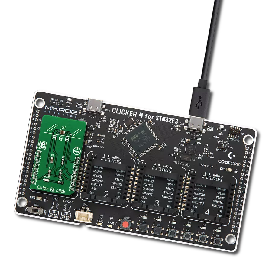
CLICKER 4 for STM32F302VCT6
Compiler
NECTO Studio
MCU
STM32F302VC
Discover a new realm of possibilities as you delve into the art and science of color sensing with our innovative solution
A
A
Hardware Overview
How does it work?
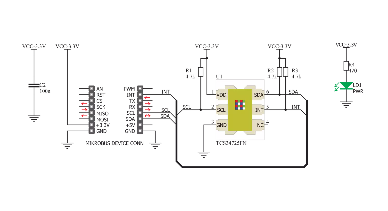
Color 7 Click is based on the TCS3472 color light to digital converter with IR filter, from ams OSRAM. The color sensor is made out of a 4x3 matrix of photosensitive elements - photodiodes, which are placed under red, green, and blue colored filters. One group of photodiodes has no color filter, thus sensing the clear light. All the photodiodes are coated with an IR resistive layer, which prevents the influence of the IR part of the spectrum on the color readings. Besides the color sensing elements, the TCS3472 has four 16bit ADCs that convert the photodiode current into a 16bit value, available for reading. Finally, the TCS3472 IC contains a state machine, which controls the operation of the IC. After the Power ON reset, the device is set in the low power mode (Sleep mode). An I2C Start condition will wake up the device and it transitions to the Idle state. After checking the content of the Enable register PON bit. If set, the device will resume in Idle mode, and after setting the AEN bit of the Enable register, the sampling cycle is started. Another bit (WEN) determines if the device will start in Wait mode, or it will start the sampling cycle, with the integration time, defined by the user firmware. Integration time affects the sensitivity and the resolution of ADCs.
After the conversion is complete, the device returns to idle state, repeating the whole cycle, depending on the states of these bits. There are two modes of measurement available on this Click board™. It can use the CONT (continuous measurement), or the CMD (single measurement) measurement modes. The CONT mode outputs data continuously, using a time delay determined by the content of the BREAK register, while the CMD mode allows one measurement to be performed per command. After a single measurement is performed, the device can fall back to the Power Down or Standby state, while working in CMD mode. This is determined by the appropriate bits in the configuration registers and allows for a lower power consumption if required by the application. The interrupt engine allows low and high thresholds to be defined. The conversion value is compared with values set as the low and high threshold, and if any of the threshold values is exceeded, the interrupt event will be generated. The interrupt will assert the INT pin of the IC, routed to the mikroBUS™ INT pin. The interrupt pin will remain asserted until host clears the interrupt flag by the appropriate command. Another interrupt engine feature is the
persistence filter. This allows the number of the consecutive threshold exceed occurrences to be made before triggering an interrupt, avoiding erratic or false interrupt triggering. This pin is an open drain topology, and when asserted, it will be driven to a LOW logic state. It is set to a HIGH state when inactive, by the pull-up resistor. The Click board™ itself uses a very low number of external components. In fact, it only uses a few resistors for pulling the I2C/INT lines to a HIGH logic level when not asserted. The low number of external components simplify the design with this IC, allowing it to be used in a wide range of applications. I2C bus lines are routed to the appropriate mikroBUS™ pins, offering simple and reliable interfacing with the host MCU. Please note that this Click board™ can work only with 3.3V MCUs and it is not 5V tolerant. The device datasheet contains all the necessary information about the registers and their values. However, the Click board™ comes supported by a library, which contains functions which greatly simplify the development of the applications, cutting time to market.


Features overview
Development board
Clicker 4 for STM32F3 is a compact development board designed as a complete solution, you can use it to quickly build your own gadgets with unique functionalities. Featuring a STM32F302VCT6, four mikroBUS™ sockets for Click boards™ connectivity, power managment, and more, it represents a perfect solution for the rapid development of many different types of applications. At its core, there is a STM32F302VCT6 MCU, a powerful microcontroller by STMicroelectronics, based on the high-
performance Arm® Cortex®-M4 32-bit processor core operating at up to 168 MHz frequency. It provides sufficient processing power for the most demanding tasks, allowing Clicker 4 to adapt to any specific application requirements. Besides two 1x20 pin headers, four improved mikroBUS™ sockets represent the most distinctive connectivity feature, allowing access to a huge base of Click boards™, growing on a daily basis. Each section of Clicker 4 is clearly marked, offering an intuitive and clean interface. This makes working with the development
board much simpler and thus, faster. The usability of Clicker 4 doesn’t end with its ability to accelerate the prototyping and application development stages: it is designed as a complete solution which can be implemented directly into any project, with no additional hardware modifications required. Four mounting holes [4.2mm/0.165”] at all four corners allow simple installation by using mounting screws. For most applications, a nice stylish casing is all that is needed to turn the Clicker 4 development board into a fully functional, custom design.

Microcontroller Overview
MCU Card / MCU

Architecture
ARM Cortex-M4
MCU Memory (KB)
256
Silicon Vendor
STMicroelectronics
Pin count
100
RAM (Bytes)
40960
Used MCU Pins
mikroBUS™ mapper
Take a closer look
Click board™ Schematic
Step by step
Project assembly

Start by selecting your development board and Click board™. Begin with the CLICKER 4 for STM32F302VCT6 as your development board.


Track your results in real time
Application Output
1. Application Output - In Debug mode, the 'Application Output' window enables real-time data monitoring, offering direct insight into execution results. Ensure proper data display by configuring the environment correctly using the provided tutorial.

2. UART Terminal - Use the UART Terminal to monitor data transmission via a USB to UART converter, allowing direct communication between the Click board™ and your development system. Configure the baud rate and other serial settings according to your project's requirements to ensure proper functionality. For step-by-step setup instructions, refer to the provided tutorial.

3. Plot Output - The Plot feature offers a powerful way to visualize real-time sensor data, enabling trend analysis, debugging, and comparison of multiple data points. To set it up correctly, follow the provided tutorial, which includes a step-by-step example of using the Plot feature to display Click board™ readings. To use the Plot feature in your code, use the function: plot(*insert_graph_name*, variable_name);. This is a general format, and it is up to the user to replace 'insert_graph_name' with the actual graph name and 'variable_name' with the parameter to be displayed.

Software Support
Library Description
This library contains API for Color 7 Click driver.
Key functions:
color7_get_color- Functions for detect colorscolor7_get_interrupt_state- Get interrut pin statecolor7_read_color_ratio- Functions for read color ratio
Open Source
Code example
The complete application code and a ready-to-use project are available through the NECTO Studio Package Manager for direct installation in the NECTO Studio. The application code can also be found on the MIKROE GitHub account.
/*!
 * \file
 * \brief Color7 Click example
 *
 * # Description
 * Demo application reads and detects colors - detected color logs on USBUART.
 *
 * The demo application is composed of two sections :
 *
 * ## Application Init
 * Configuring Clicks and log objects.
 * Settings the Click in the default configuration.
 *
 * ## Application Task
 * Reads light color and checks which color of light is detected by the sensor
 * If the light color is detected, the detected color message is logged on the USBUART.
 *
 * *note:*
 * Light source must be pointed towards sensor in order for sensor to
 * detect light source color correctly.
 * We used the HSL color palette on the monitor as an example.
 *
 * \author Katarina Perendic
 *
 */
// ------------------------------------------------------------------- INCLUDES

#include "board.h"
#include "log.h"
#include "color7.h"

// ------------------------------------------------------------------ VARIABLES

static color7_t color7;
static log_t logger;

// ------------------------------------------------------ APPLICATION FUNCTIONS

void application_init ( void )
{
    log_cfg_t log_cfg;
    color7_cfg_t cfg;

    /**
     * Logger initialization.
     * Default baud rate: 115200
     * Default log level: LOG_LEVEL_DEBUG
     * @note If USB_UART_RX and USB_UART_TX
     * are defined as HAL_PIN_NC, you will
     * need to define them manually for log to work.
     * See @b LOG_MAP_USB_UART macro definition for detailed explanation.
     */
    LOG_MAP_USB_UART( log_cfg );
    log_init( &logger, &log_cfg );
    log_info( &logger, "---- Application Init ----" );

    //  Click initialization.

    color7_cfg_setup( &cfg );
    COLOR7_MAP_MIKROBUS( cfg, MIKROBUS_1 );
    color7_init( &color7, &cfg );

    color7_default_cfg( &color7 );
    log_info( &logger, "---- Start measurement ----" );
}

void application_task ( void )
{
    uint8_t color;

    //  Task implementation.

    color = color7_get_color( &color7 );

    switch( color )
    {
        case 1:
        {
            log_printf( &logger, "--- Color: ORANGE \r\n" );
            break;
        }
        case 2:
        {
            log_printf( &logger, "--- Color: RED \r\n" );
            break;
        }
        case 3:
        {
            log_printf( &logger, "--- Color: PINK \r\n" );
            break;
        }
        case 4:
        {
            log_printf( &logger, "--- Color: PURPLE \r\n" );
            break;
        }
        case 5:
        {
            log_printf( &logger, "--- Color: BLUE \r\n" );
            break;
        }
        case 6:
        {
            log_printf( &logger, "--- Color: CYAN \r\n" );
            break;
        }
        case 7:
        {
            log_printf( &logger, "--- Color: GREEN \r\n" );
            break;
        }
        case 8:
        {
            log_printf( &logger, "--- Color: YELLOW \r\n" );
            break;
        }
        default:
        {
            // log_printf( &logger, "--- Color: UNRECOGNIZABLE \r\n" );
            break;
        }
    }
    Delay_100ms();
}

int main ( void )
{
    /* Do not remove this line or clock might not be set correctly. */
    #ifdef PREINIT_SUPPORTED
    preinit();
    #endif

    application_init( );

    for ( ; ; )
    {
        application_task( );
    }

    return 0;
}


// ------------------------------------------------------------------------ END
Additional Support
Resources
Category:Optical


