Accurately capture and analyze colors with TCS3771 and STM32L4A6RG for a multitude of applications
Colors in the spotlight

Published Sep 19, 2023
Click board™
Color 3 Click
Dev. board
Fusion for STM32 v8
Compiler
NECTO Studio
MCU
STM32L4A6RG
Learn how this cutting-edge RGB color sensing technology can elevate your projects and products by ensuring true-to-life color reproduction and enhanced visual experiences
A
A
Hardware Overview
How does it work?
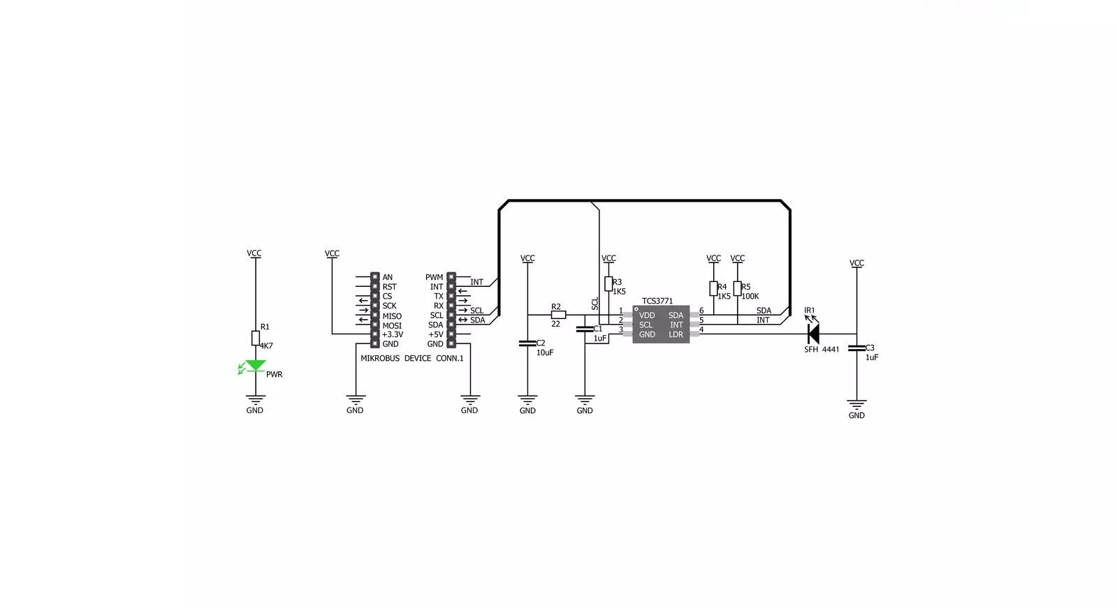
Color 3 Click is based on TCS3771, a color light-to-light digital convertor with proximity sensing from ams AG, providing fast and accurate spectral measurements. The TCS3771 contains a 4×4 photodiode array comprising red-/green-/blue-filtered and clear photodiodes (four of each type), internal amplifiers, ADCs, accumulators, clocks, buffers, comparators, a state machine, and a serial interface. Four integrated ADCs convert the amplified photodiode currents simultaneously to a digital value, providing up to 16 bits of resolution, transferring the result to the data registers, and maintaining data integrity. The TCS3771 has a high sensitivity making this board suitable for operation behind dark glass. Proximity sensing uses an external light source, the SFH4441, an onboard IR
LED from ams AG, to emit light towards the reflective surface, after which the TCS3771 measures the amount of reflected light from an object which is in the light path. A TCS3771‘s internal LED driver provides a software-configurable constant current sink of 12.5mA, 25mA, 50mA, or 100mA of current, alongside programmable proximity LED pulses from 1 to 255. The amount of light detected from a reflective surface is then used to determine an object’s proximity to the sensor. This Click board™ communicates with MCU using the standard I2C 2-Wire interface to read data and configure settings, supporting a Fast Mode operation up to 400kHz. Besides, it also possesses an interrupt feature, routed to the INT pin of the mikroBUS™
socket, which serves as an alarm or monitoring function to determine whether the color light or proximity values exceed the upper threshold or go below the lower threshold. The user can also configure the persistency of the interrupt pin, which reduces the possibility of false triggers, such as noise or sudden spikes in color light conditions. This Click board™ can be operated only with a 3.3V logic voltage level. The board must perform appropriate logic voltage level conversion before using MCUs with different logic levels. Also, it comes equipped with a library containing functions and an example code that can be used as a reference for further development.


Features overview
Development board
Fusion for STM32 v8 is a development board specially designed for the needs of rapid development of embedded applications. It supports a wide range of microcontrollers, such as different 32-bit ARM® Cortex®-M based MCUs from STMicroelectronics, regardless of their number of pins, and a broad set of unique functions, such as the first-ever embedded debugger/programmer over WiFi. The development board is well organized and designed so that the end-user has all the necessary elements, such as switches, buttons, indicators, connectors, and others, in one place. Thanks to innovative manufacturing technology, Fusion for STM32 v8 provides a fluid and immersive working experience, allowing
access anywhere and under any circumstances at any time. Each part of the Fusion for STM32 v8 development board contains the components necessary for the most efficient operation of the same board. An advanced integrated CODEGRIP programmer/debugger module offers many valuable programming/debugging options, including support for JTAG, SWD, and SWO Trace (Single Wire Output)), and seamless integration with the Mikroe software environment. Besides, it also includes a clean and regulated power supply module for the development board. It can use a wide range of external power sources, including a battery, an external 12V power supply, and a power source via the USB Type-C (USB-C) connector.
Communication options such as USB-UART, USB HOST/DEVICE, CAN (on the MCU card, if supported), and Ethernet is also included. In addition, it also has the well-established mikroBUS™ standard, a standardized socket for the MCU card (SiBRAIN standard), and two display options for the TFT board line of products and character-based LCD. Fusion for STM32 v8 is an integral part of the Mikroe ecosystem for rapid development. Natively supported by Mikroe software tools, it covers many aspects of prototyping and development thanks to a considerable number of different Click boards™ (over a thousand boards), the number of which is growing every day.

Microcontroller Overview
MCU Card / MCU
Type
8th Generation
Architecture
ARM Cortex-M4
MCU Memory (KB)
1024
Silicon Vendor
STMicroelectronics
Pin count
64
RAM (Bytes)
327680
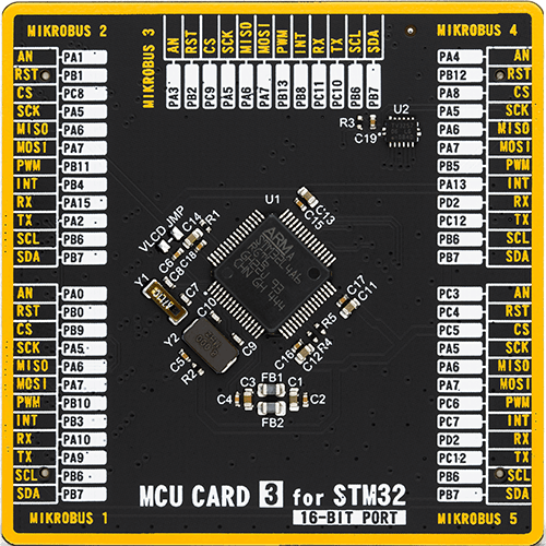
Used MCU Pins
mikroBUS™ mapper
Take a closer look
Click board™ Schematic
Step by step
Project assembly

Start by selecting your development board and Click board™. Begin with the Fusion for STM32 v8 as your development board.


Track your results in real time
Application Output
1. Application Output - In Debug mode, the 'Application Output' window enables real-time data monitoring, offering direct insight into execution results. Ensure proper data display by configuring the environment correctly using the provided tutorial.

2. UART Terminal - Use the UART Terminal to monitor data transmission via a USB to UART converter, allowing direct communication between the Click board™ and your development system. Configure the baud rate and other serial settings according to your project's requirements to ensure proper functionality. For step-by-step setup instructions, refer to the provided tutorial.

3. Plot Output - The Plot feature offers a powerful way to visualize real-time sensor data, enabling trend analysis, debugging, and comparison of multiple data points. To set it up correctly, follow the provided tutorial, which includes a step-by-step example of using the Plot feature to display Click board™ readings. To use the Plot feature in your code, use the function: plot(*insert_graph_name*, variable_name);. This is a general format, and it is up to the user to replace 'insert_graph_name' with the actual graph name and 'variable_name' with the parameter to be displayed.

Software Support
Library Description
This library contains API for Color 3 Click driver.
Key functions:
color3_get_rgbc_data- This function reads data from 4 channels (Red, Green, Blue, Clear)color3_rgbc_to_hsl- This function converts RGBC (red, green, blue, clear) to HSL (hue, saturation, lightness) color valuecolor3_get_color- This function returns the color name flag from the input HSL color.
Open Source
Code example
The complete application code and a ready-to-use project are available through the NECTO Studio Package Manager for direct installation in the NECTO Studio. The application code can also be found on the MIKROE GitHub account.
/*!
 * \file
 * \brief Color 3 Click example
 *
 * # Description
 * This example demonstrates the use of Color 3 Click board by reading data
 * from RGBC channels and converting them to HSL color and displaying those data as
 * well as the detected color name on the USB UART.
 *
 * The demo application is composed of two sections :
 *
 * ## Application Init
 * Initializes the driver and performs the Click default configuration.
 *
 * ## Application Task
 * Reads the values of all channels and converts them to HSL color and displays those data
 * as well as the detected color name on the USB UART every 500ms approximately.
 *
 * \author MikroE Team
 *
 */
// ------------------------------------------------------------------- INCLUDES

#include "board.h"
#include "log.h"
#include "color3.h"

// ------------------------------------------------------------------ VARIABLES

static color3_t color3;
static log_t logger;

void application_init ( void )
{
    log_cfg_t log_cfg;
    color3_cfg_t cfg;

    /**
     * Logger initialization.
     * Default baud rate: 115200
     * Default log level: LOG_LEVEL_DEBUG
     * @note If USB_UART_RX and USB_UART_TX
     * are defined as HAL_PIN_NC, you will
     * need to define them manually for log to work.
     * See @b LOG_MAP_USB_UART macro definition for detailed explanation.
     */
    LOG_MAP_USB_UART( log_cfg );
    log_init( &logger, &log_cfg );
    log_info( &logger, "---- Application Init ----" );

    //  Click initialization.
    color3_cfg_setup( &cfg );
    COLOR3_MAP_MIKROBUS( cfg, MIKROBUS_1 );
    color3_init( &color3, &cfg );
    Delay_ms ( 100 );

    color3_set_default_settings( &color3 );
    Delay_ms ( 1000 );

    log_printf( &logger, "-----------------\r\n" );
    log_printf( &logger, " Color 3  Click  \r\n" );
    log_printf( &logger, "-----------------\r\n" );
}

void application_task ( void )
{
    color3_channels_t rgbc;
    if ( COLOR3_OK == color3_get_rgbc_data ( &color3, &rgbc ) )
    {
        color3_hsl_t hsl;
        color3_rgbc_to_hsl ( &color3, &rgbc, &hsl );
        log_printf ( &logger, "\r\n Red: %u\r\n", rgbc.red );
        log_printf ( &logger, " Green: %u\r\n", rgbc.green );
        log_printf ( &logger, " Blue: %u\r\n", rgbc.blue );
        log_printf ( &logger, " Clear: %u\r\n", rgbc.clear );
        log_printf ( &logger, " Hue: %.1f deg\r\n", hsl.hue );
        log_printf ( &logger, " Saturation: %.1f %%\r\n", hsl.saturation );
        log_printf ( &logger, " Lightness: %.1f %%\r\n", hsl.lightness );
        log_printf ( &logger, " Dominated color: " );
        switch ( color3_get_color ( &hsl ) )
        {
            case COLOR3_RED_COLOR:
            {
                log_printf ( &logger, "RED\r\n" );
                break;
            }
            case COLOR3_YELLOW_COLOR:
            {
                log_printf ( &logger, "YELLOW\r\n" );
                break;
            }
            case COLOR3_GREEN_COLOR:
            {
                log_printf ( &logger, "GREEN\r\n" );
                break;
            }
            case COLOR3_CYAN_COLOR:
            {
                log_printf ( &logger, "CYAN\r\n" );
                break;
            }
            case COLOR3_BLUE_COLOR:
            {
                log_printf ( &logger, "BLUE\r\n" );
                break;
            }
            case COLOR3_MAGENTA_COLOR:
            {
                log_printf ( &logger, "MAGENTA\r\n" );
                break;
            }
            case COLOR3_WHITE_COLOR:
            {
                log_printf ( &logger, "WHITE\r\n" );
                break;
            }
            case COLOR3_BLACK_COLOR:
            {
                log_printf ( &logger, "BLACK\r\n" );
                break;
            }
            default:
            {
                log_printf ( &logger, "UNKNOWN\r\n" );
                break;
            }
        }
    }
    Delay_ms ( 500 );
}

int main ( void )
{
    /* Do not remove this line or clock might not be set correctly. */
    #ifdef PREINIT_SUPPORTED
    preinit();
    #endif

    application_init( );

    for ( ; ; )
    {
        application_task( );
    }

    return 0;
}


// ------------------------------------------------------------------------ END


