Unlock the full potential of your DC motors with TLE9201SG and STM32L496AG
Experience the next-level motor control
Published Jul 22, 2025
Click board™
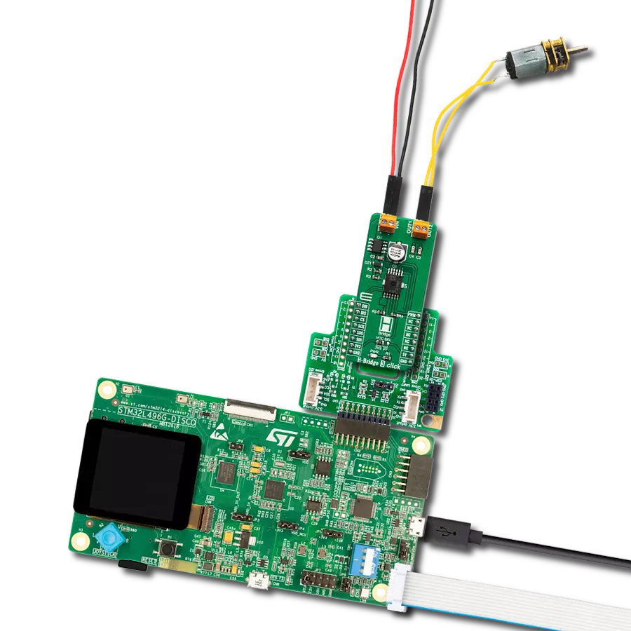
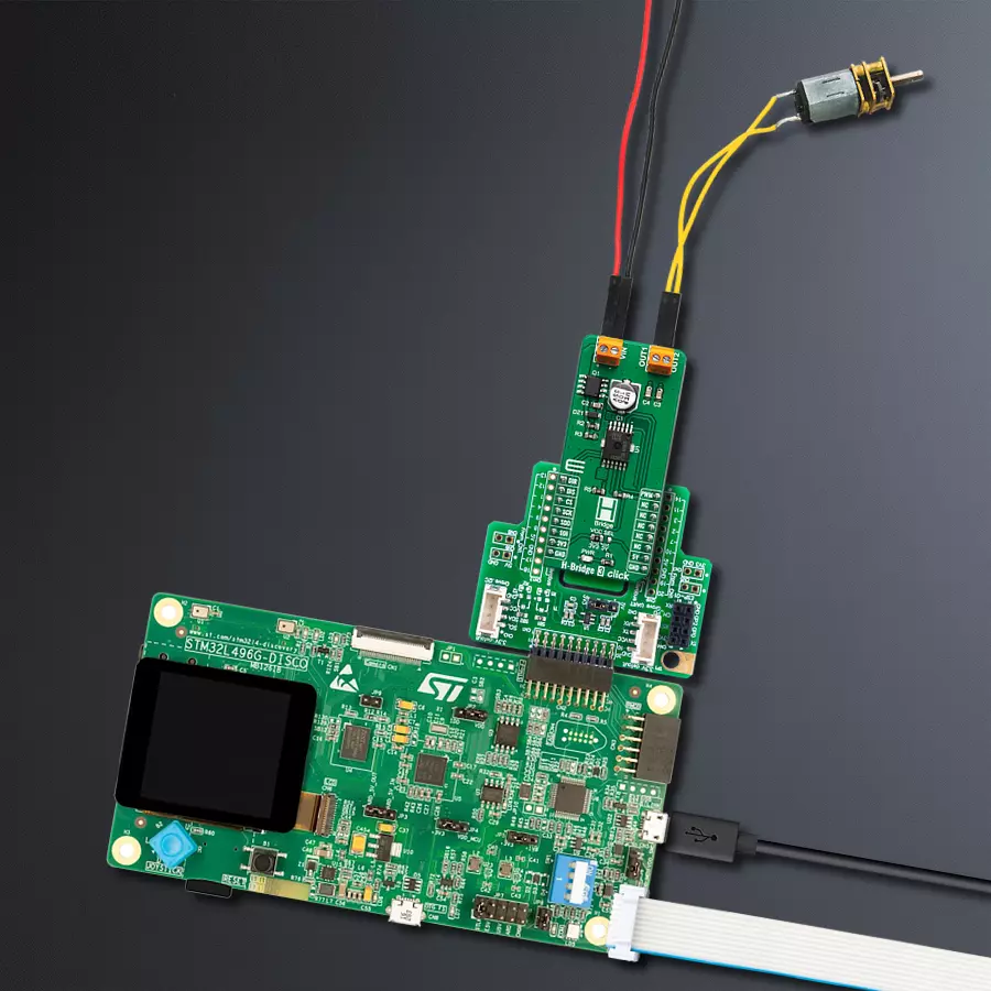
H-Bridge 3 Click
Dev. board
Discovery kit with STM32L496AG MCU
Compiler
NECTO Studio
MCU
STM32L496AG
With our H-Bridge motor driver solution, you can effortlessly control the rotation and torque of your DC motors, allowing for smooth and precise movement in robotics, automation, and more
A
A
Hardware Overview
How does it work?
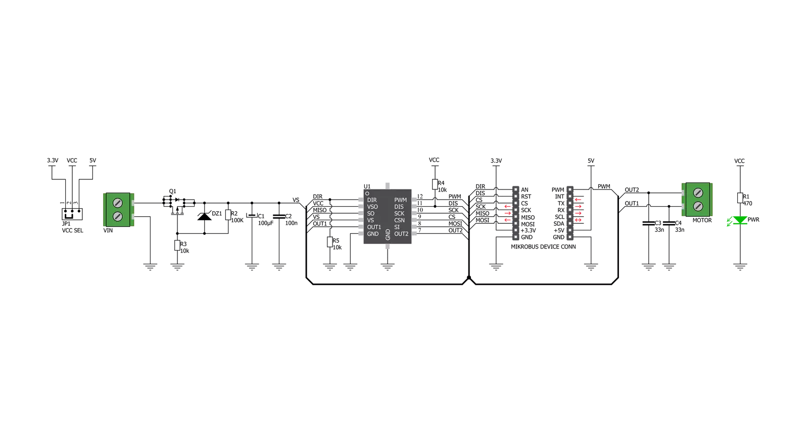
H-Bridge 3 Click is based on the TLE9201SG, an H-Bridge DC motor driver, with up to 28V and 6A, from Infineon. This IC is an efficient integrated H-bridge driver with a low RDS ON output per switch. H-bridge, in general, allows the current to flow in one or another direction. All internal supply voltages are derived from the external VIN connector. A charge pump provides the gate voltage for the high-side switches. The output buffer of the digital output SO is supplied by the pin VSO. Therefore the output logic level at SO can be easily configured for 3.3 V or 5 V logic by moving the VCC SEL jumper to the respective voltage. The output stages consist of four n-channel MOSFETs in an H-bridge configuration.
The outputs are protected against short circuits and over-temperature. The bridge is controlled using the inputs PWM and DIR. The signal at DIR defines the direction of the driven DC motor, whereas the PWM signal sets the duty cycle. The outputs can be set tristate (i.e., high side and low side switches are turned off) by setting DIS to a high level. The TLE9201SG is equipped with a “Serial Peripheral Interface“ (SPI) for diagnosis purposes. The H-bridge 3 click is configured as a “slave” device. This means that the host microcontroller, as the master, is providing the chip select (CS) and the clock signal (SCK). A data transfer on the SPI bus is initiated with a falling edge on CS and is terminated by a rising edge
on CS. The serial input pin SI data is sampled with the falling edge of SCK, and the rising clock edge determines the serial data output at MISO. The data is transferred “MSB first. The word length of the SPI is 8-bit. Please note that there is no check for the number of clocks within an SPI frame. Any low pulse at the CS line will be regarded as one frame. This Click board™ can operate with either 3.3V or 5V logic voltage levels selected via the VCC SEL jumper. This way, both 3.3V and 5V capable MCUs can use the communication lines properly. However, the Click board™ comes equipped with a library containing easy-to-use functions and an example code that can be used, as a reference, for further development.

Features overview
Development board
The 32L496GDISCOVERY Discovery kit serves as a comprehensive demonstration and development platform for the STM32L496AG microcontroller, featuring an Arm® Cortex®-M4 core. Designed for applications that demand a balance of high performance, advanced graphics, and ultra-low power consumption, this kit enables seamless prototyping for a wide range of embedded solutions. With its innovative energy-efficient
architecture, the STM32L496AG integrates extended RAM and the Chrom-ART Accelerator, enhancing graphics performance while maintaining low power consumption. This makes the kit particularly well-suited for applications involving audio processing, graphical user interfaces, and real-time data acquisition, where energy efficiency is a key requirement. For ease of development, the board includes an onboard ST-LINK/V2-1
debugger/programmer, providing a seamless out-of-the-box experience for loading, debugging, and testing applications without requiring additional hardware. The combination of low power features, enhanced memory capabilities, and built-in debugging tools makes the 32L496GDISCOVERY kit an ideal choice for prototyping advanced embedded systems with state-of-the-art energy efficiency.

Microcontroller Overview
MCU Card / MCU

Architecture
ARM Cortex-M4
MCU Memory (KB)
1024
Silicon Vendor
STMicroelectronics
Pin count
169
RAM (Bytes)
327680
You complete me!
Accessories
DC Gear Motor - 430RPM (3-6V) represents an all-in-one combination of a motor and gearbox, where the addition of gear leads to a reduction of motor speed while increasing the torque output. This gear motor has a spur gearbox, making it a highly reliable solution for applications with lower torque and speed requirements. The most critical parameters for gear motors are speed, torque, and efficiency, which are, in this case, 520RPM with no load and 430RPM at maximum efficiency, alongside a current of 60mA and a torque of 50g.cm. Rated for a 3-6V operational voltage range and clockwise/counterclockwise rotation direction, this motor represents an excellent solution for many functions initially performed by brushed DC motors in robotics, medical equipment, electric door locks, and much more.

Used MCU Pins
mikroBUS™ mapper
Take a closer look
Click board™ Schematic
Step by step
Project assembly

Start by selecting your development board and Click board™. Begin with the Discovery kit with STM32L496AG MCU as your development board.


Track your results in real time
Application Output
1. Application Output - In Debug mode, the 'Application Output' window enables real-time data monitoring, offering direct insight into execution results. Ensure proper data display by configuring the environment correctly using the provided tutorial.

2. UART Terminal - Use the UART Terminal to monitor data transmission via a USB to UART converter, allowing direct communication between the Click board™ and your development system. Configure the baud rate and other serial settings according to your project's requirements to ensure proper functionality. For step-by-step setup instructions, refer to the provided tutorial.

3. Plot Output - The Plot feature offers a powerful way to visualize real-time sensor data, enabling trend analysis, debugging, and comparison of multiple data points. To set it up correctly, follow the provided tutorial, which includes a step-by-step example of using the Plot feature to display Click board™ readings. To use the Plot feature in your code, use the function: plot(*insert_graph_name*, variable_name);. This is a general format, and it is up to the user to replace 'insert_graph_name' with the actual graph name and 'variable_name' with the parameter to be displayed.

Software Support
Library Description
This library contains API for H-Bridge 3 Click driver.
Key functions:
hbridge3_set_duty_cycle- This function sets the PWM duty cyclehbridge3_spi- This function sends SPI command and receives response to command senthbridge3_generic_transfer- Generic SPI transfer, for sending and receiving packages
Open Source
Code example
The complete application code and a ready-to-use project are available through the NECTO Studio Package Manager for direct installation in the NECTO Studio. The application code can also be found on the MIKROE GitHub account.
/*!
 * @file
 * @brief HBridge3 Click example
 *
 * # Description
 * H-bridge in general, allows the current to flow in one or another direction.
 * This Click is used for driving a H-Bridge motor by changing output states.
 * The outputs can be pulse width modulated at frequencies up to 20kHz by means of PWM/DIR control.
 *
 * The demo application is composed of two sections :
 *
 * ## Application Init
 * Initializes SPI and LOG modules, AN, RST, CS and PWM pins
 *
 * ## Application Task
 * This example demonstrates the use of H-Bridge 3 Click board,
 * by running dc motor in both directions - increasing and decreasing PWM duty cycle.
 * Results are being sent to the Usart Terminal where you can track their changes.
 *
 *
 * @author Nikola Peric
 *
 */
// ------------------------------------------------------------------- INCLUDES

#include "board.h"
#include "log.h"
#include "hbridge3.h"

// ------------------------------------------------------------------ VARIABLES

static hbridge3_t hbridge3;
static log_t logger;
uint8_t motor_direction = 0;

// ------------------------------------------------------ APPLICATION FUNCTIONS

void application_init ( void )
{
    log_cfg_t log_cfg;
    hbridge3_cfg_t cfg;

    /**
     * Logger initialization.
     * Default baud rate: 115200
     * Default log level: LOG_LEVEL_DEBUG
     * @note If USB_UART_RX and USB_UART_TX
     * are defined as HAL_PIN_NC, you will
     * need to define them manually for log to work.
     * See @b LOG_MAP_USB_UART macro definition for detailed explanation.
     */
    LOG_MAP_USB_UART( log_cfg );
    log_init( &logger, &log_cfg );
    log_info( &logger, "---- Application Init ----" );

    //  Click initialization.

    hbridge3_cfg_setup( &cfg );
    HBRIDGE3_MAP_MIKROBUS( cfg, MIKROBUS_1 );
    hbridge3_init( &hbridge3, &cfg );
    Delay_ms ( 500 );

    hbridge3_pwm_start( &hbridge3 );
    log_info( &logger, "---- Application Task ----" );
    log_printf( &logger, "> CLOCKWISE <\r\n" );
}

void application_task ( void )
{
    static int8_t duty_cnt = 1;
    static int8_t duty_inc = 1;
    float duty = duty_cnt / 10.0;


    hbridge3_set_duty_cycle ( &hbridge3, duty );
    log_printf( &logger, " Duty: %d%%\r\n", ( uint16_t )( duty_cnt * 10 ) );
    Delay_ms ( 500 );

    if ( 10 == duty_cnt )
    {
        duty_inc = -1;
    }
    else if ( 0 == duty_cnt )
    {
        duty_inc = 1;

        if ( motor_direction == 1 )
        {
            log_printf( &logger, "> COUNTER CLOCKWISE <\r\n" );
            motor_direction = 0;
             hbridge3_dir_set ( &hbridge3 , 0 );
        }
        else if ( motor_direction == 0 )
        {
            log_printf( &logger, "> CLOCKWISE <\r\n" );
            motor_direction = 1;
            hbridge3_dir_set ( &hbridge3 , 1 );
        }
    }
    duty_cnt += duty_inc;
}

int main ( void )
{
    /* Do not remove this line or clock might not be set correctly. */
    #ifdef PREINIT_SUPPORTED
    preinit();
    #endif

    application_init( );

    for ( ; ; )
    {
        application_task( );
    }

    return 0;
}


// ------------------------------------------------------------------------ END
Additional Support
Resources
Category:Brushed