Elevate your power game with TPS62912 and STM32F205RB
Synchronous step-down brilliance!

Published Aug 01, 2023
Click board™
Buck 16 Click
Dev. board
Fusion for STM32 v8
Compiler
NECTO Studio
MCU
STM32F205RB
Whether in industrial automation or consumer electronics, the buck step-down converter is a go-to solution for maintaining a stable voltage supply in various applications
A
A
Hardware Overview
How does it work?
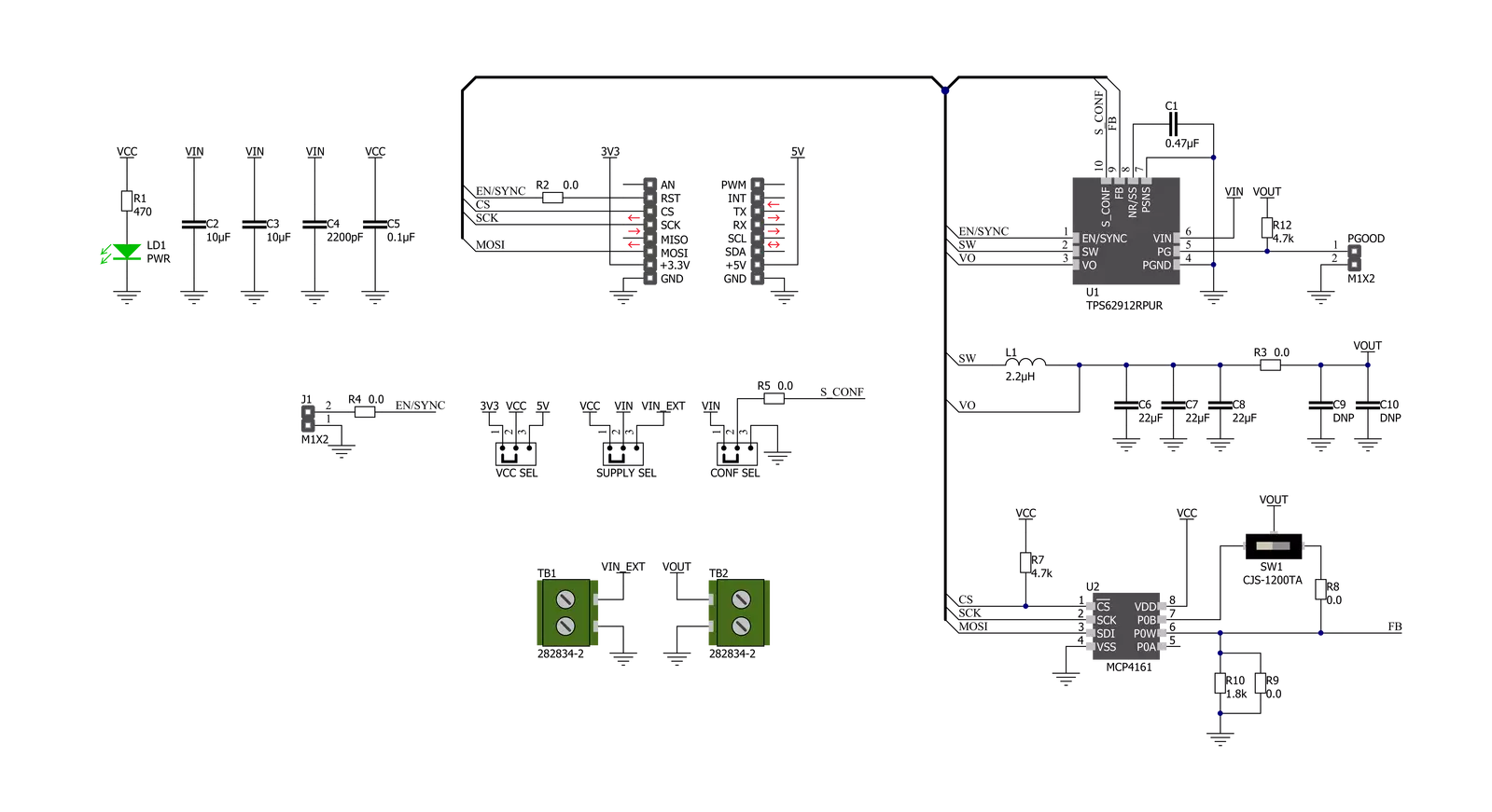
Buck 16 Click is based on the TPS62912, a low-noise, low-ripple synchronous buck converter with a fixed-frequency current-mode from Texas Instruments. This converter has a filtered internal reference that achieves a low-noise output similar to low-noise LDOs. Besides, it has an output-voltage error of less than 1%, which helps ensure tight output-voltage accuracy and lower output-voltage ripple by using a switching frequency of either 2.2MHz or 1MHz. This Click board™ is suitable for noise-sensitive applications using an LDO for post-regulation. This Click board™ communicates with MCU using one GPIO pin and a 3-wire SPI serial interface. The device-enable feature, routed to the RST pin of the mikroBUS™ socket, optimizes power consumption and is used for power ON/OFF purposes (driver operation permission). Once the Click board™ is enabled,
the operation mode is set by the configuration of the CONF SEL (Smart Configuration) jumper by positioning the SMD jumper to an appropriate position marked as VIN or GND. Besides this pin is also used for device synchronization. Once an external clock signal, which must be within the clock synchronization frequency range set by the Smart Configuration jumper, is applied to this pin through an onboard header marked as SYNC, the device is enabled and reads the configuration of the Smart Configuration pin. When this signal changes from a clock to a static high, the device switches from an external to an internal clock. With all that, this device also has a power-good output available on the onboard header labeled PGOOD. The PGOOD pin goes into a high impedance state once the feedback pin voltage, obtained by the MCP4161 digital potentiometer
and controlled by the DIGI POT, is above 95% of the nominal voltage and is driven low once the voltage falls below typically 90% of the nominal voltage. The power-good signal can sequence multiple rails by connecting to the enable pin of other converters. This Click board™ can operate with both 3.3V and 5V logic voltage levels selected via the VCC SEL jumper. It allows both 3.3V and 5V capable MCUs to use the communication lines properly. Additionally, there is a possibility for the TPS62912 power supply selection via jumper labeled as VIN SEL to supply the TPS62912 from an external power supply terminal in the range from 3 to 17V or with VCC voltage levels from mikroBUS™ power rails. Also, this Click board™ comes equipped with a library containing easy-to-use functions and an example code that can be used, as a reference, for further development.

Features overview
Development board
Fusion for STM32 v8 is a development board specially designed for the needs of rapid development of embedded applications. It supports a wide range of microcontrollers, such as different 32-bit ARM® Cortex®-M based MCUs from STMicroelectronics, regardless of their number of pins, and a broad set of unique functions, such as the first-ever embedded debugger/programmer over WiFi. The development board is well organized and designed so that the end-user has all the necessary elements, such as switches, buttons, indicators, connectors, and others, in one place. Thanks to innovative manufacturing technology, Fusion for STM32 v8 provides a fluid and immersive working experience, allowing
access anywhere and under any circumstances at any time. Each part of the Fusion for STM32 v8 development board contains the components necessary for the most efficient operation of the same board. An advanced integrated CODEGRIP programmer/debugger module offers many valuable programming/debugging options, including support for JTAG, SWD, and SWO Trace (Single Wire Output)), and seamless integration with the Mikroe software environment. Besides, it also includes a clean and regulated power supply module for the development board. It can use a wide range of external power sources, including a battery, an external 12V power supply, and a power source via the USB Type-C (USB-C) connector.
Communication options such as USB-UART, USB HOST/DEVICE, CAN (on the MCU card, if supported), and Ethernet is also included. In addition, it also has the well-established mikroBUS™ standard, a standardized socket for the MCU card (SiBRAIN standard), and two display options for the TFT board line of products and character-based LCD. Fusion for STM32 v8 is an integral part of the Mikroe ecosystem for rapid development. Natively supported by Mikroe software tools, it covers many aspects of prototyping and development thanks to a considerable number of different Click boards™ (over a thousand boards), the number of which is growing every day.

Microcontroller Overview
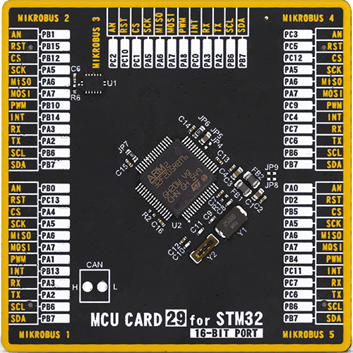
MCU Card / MCU
Type
8th Generation
Architecture
ARM Cortex-M3
MCU Memory (KB)
128
Silicon Vendor
STMicroelectronics
Pin count
64
RAM (Bytes)
65536
Used MCU Pins
mikroBUS™ mapper
Take a closer look
Click board™ Schematic
Step by step
Project assembly

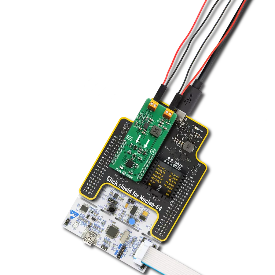
Start by selecting your development board and Click board™. Begin with the Fusion for STM32 v8 as your development board.


Track your results in real time
Application Output
1. Application Output - In Debug mode, the 'Application Output' window enables real-time data monitoring, offering direct insight into execution results. Ensure proper data display by configuring the environment correctly using the provided tutorial.

2. UART Terminal - Use the UART Terminal to monitor data transmission via a USB to UART converter, allowing direct communication between the Click board™ and your development system. Configure the baud rate and other serial settings according to your project's requirements to ensure proper functionality. For step-by-step setup instructions, refer to the provided tutorial.

3. Plot Output - The Plot feature offers a powerful way to visualize real-time sensor data, enabling trend analysis, debugging, and comparison of multiple data points. To set it up correctly, follow the provided tutorial, which includes a step-by-step example of using the Plot feature to display Click board™ readings. To use the Plot feature in your code, use the function: plot(*insert_graph_name*, variable_name);. This is a general format, and it is up to the user to replace 'insert_graph_name' with the actual graph name and 'variable_name' with the parameter to be displayed.

Software Support
Library Description
This library contains API for Buck 16 Click driver.
Key functions:
buck16_enable_output- Enable/Disable voltage outputbuck16_set_potentiometer- Set potentiometer resistivitybuck16_set_output- Set output voltage
Open Source
Code example
The complete application code and a ready-to-use project are available through the NECTO Studio Package Manager for direct installation in the NECTO Studio. The application code can also be found on the MIKROE GitHub account.
/*!
 * @file main.c
 * @brief Buck16 Click example
 *
 * # Description
 * This example showcases ability of the device to
 * control voltage output of device. Output voltage
 * can range from 800 to 5500 depending of VIN. By default
 * it will go from 800 to 3300 VIN==VCC.
 *
 * The demo application is composed of two sections :
 *
 * ## Application Init
 * Initialization of communication modules (SPI, UART)
 * and additional pin for enabling output and sets it to
 * high.
 *
 *
 * ## Application Task
 * Sets voltage output first to 900mV then to 2500 mV.
 * Then disables and enables output by toggling pin.
 * In the end sets output value to 1500mV.
 *
 * @author Luka Filipovic
 *
 */

#include "board.h"
#include "log.h"
#include "buck16.h"

static buck16_t buck16;
static log_t logger;

void application_init ( void )
{
    log_cfg_t log_cfg;          /**< Logger config object. */
    buck16_cfg_t buck16_cfg;    /**< Click config object. */

    /**
     * Logger initialization.
     * Default baud rate: 115200
     * Default log level: LOG_LEVEL_DEBUG
     * @note If USB_UART_RX and USB_UART_TX
     * are defined as HAL_PIN_NC, you will
     * need to define them manually for log to work.
     * See @b LOG_MAP_USB_UART macro definition for detailed explanation.
     */
    LOG_MAP_USB_UART( log_cfg );
    log_init( &logger, &log_cfg );
    log_printf( &logger, "\r> Application Init <\r\n" );

    // Click initialization.
    buck16_cfg_setup( &buck16_cfg );
    BUCK16_MAP_MIKROBUS( buck16_cfg, MIKROBUS_1 );
    err_t init_flag  = buck16_init( &buck16, &buck16_cfg );
    if ( SPI_MASTER_ERROR == init_flag )
    {
        log_error( &logger, " Application Init Error. " );
        log_info( &logger, " Please, run program again... " );

        for ( ; ; );
    }

    buck16_enable_output( &buck16, 1 );
    log_printf( &logger, "> Application Task <\r\n" );
}

void application_task ( void )
{
    log_printf( &logger, " > Setting output to 0.9V\r\n" );
    buck16_set_output( &buck16, 900 );
    Delay_ms ( 1000 );
    Delay_ms ( 1000 );
    Delay_ms ( 1000 );
    Delay_ms ( 1000 );
    Delay_ms ( 1000 );
    log_printf( &logger, " > Setting output to 2.5V\r\n" );
    buck16_set_output( &buck16, 2500 );
    Delay_ms ( 1000 );
    Delay_ms ( 1000 );
    Delay_ms ( 1000 );
    Delay_ms ( 1000 );
    Delay_ms ( 1000 );
    log_printf( &logger, " > Disable output\r\n" );
    buck16_enable_output( &buck16, 0 );
    Delay_ms ( 1000 );
    Delay_ms ( 1000 );
    Delay_ms ( 1000 );
    log_printf( &logger, " > Enable output\r\n" );
    buck16_enable_output( &buck16, 1 );
    Delay_ms ( 1000 );
    Delay_ms ( 1000 );
    Delay_ms ( 1000 );
    log_printf( &logger, " > Setting output to 1.5V\r\n" );
    buck16_set_output( &buck16, 1500 );
    Delay_ms ( 1000 );
    Delay_ms ( 1000 );
    Delay_ms ( 1000 );
    Delay_ms ( 1000 );
    Delay_ms ( 1000 );
}

int main ( void )
{
    /* Do not remove this line or clock might not be set correctly. */
    #ifdef PREINIT_SUPPORTED
    preinit();
    #endif

    application_init( );

    for ( ; ; )
    {
        application_task( );
    }

    return 0;
}

// ------------------------------------------------------------------------ END