Determine if something is nearby or not using VCNL4035X01 and PIC24EP512GU814
Unlocking the potential of close-range sensing

Published Oct 14, 2023
Click board™
Proximity 5 Click
Dev. board
UNI-DS v8
Compiler
NECTO Studio
MCU
PIC24EP512GU814
Discover how our cutting-edge proximity detection technology is reshaping how we interact with the world around us
A
A
Hardware Overview
How does it work?
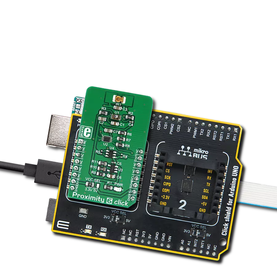
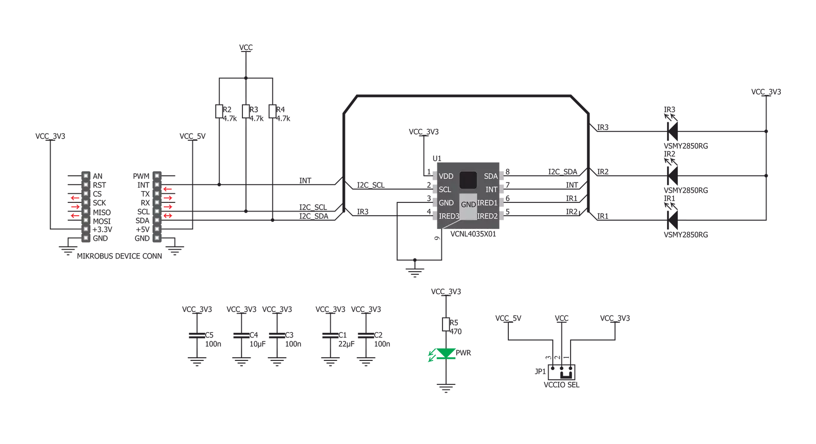
Proximity 5 Click is based on the VCNL4035X01, a fully integrated proximity and ambient light sensor with I2C interface and the interrupt function for gesture applications, from Vishay Semiconductors. This sensor features very advanced 16bit Ambient Light Sensor (ALS) which makes use of the proprietary Filtron™ technology, providing spectral response sensitivity near to human eye. The ALS sensor also effectively cancels out infrared light, has immunity to the flickering of fluorescent light sources and has a programmable detection range, with the resolution of up to 0.004 lux per count. The Proximity Sensing (PS) section of the VCNL4035X01 J IC implements several solutions for the improved proximity detection of objects of any color. It relies on detection of the reflected IR light from the emitting LEDs. Features such as the immunity to a red glow, intelligent crosstalk phenomenon reduction, smart persistence scheme, programmable IR LED current, and selectable sampling resolution, help in achieving a reliable and accurate proximity detection. The processed readings of the ALS and PS sections can be fetched from the respective registers via the I2C interface. The I2C bus lines are routed to the respective mikroBUS™ I2C pins:
SCL is the I2C clock and SDA is the I2C data line. The VCNL4035X01 J sensor IC integrates three independent LED drivers, which can drive the external IR LEDs with up to 200mA, allowing a wide range of external IR LEDs to be used. Proximity 5 click uses the VSMY2850RG LEDs, 850nm IR LEDs with lenses, from Vishay. These IR LEDs are operating within the wavelength range which is recommended by the sensor manufacturer. The IR LEDs can be driven by the variable duty cycle, which affects the total power consumption, as well as the PS response time. The VCNL4035X01 J sensor IC is powered by the 3.3V rail from the mikroBUS™ directly. However, since it uses the I2C communication protocol, it is possible to choose the voltage for the I2C pull-up resistors between 3.3V and 5V. This is accomplished by moving the SMD jumper labeled as VCCIO SEL to the appropriate position. This jumper allows communication with both 3.3V and 5V MCUs. Proximity 5 click offers programmable interrupt engine. The INT pin is routed to the mikroBUS™ INT pin and it is pulled up by the onboard resistor. When asserted, it is driven to a LOW logic level. The interrupt can be programmed for a wide range of events for both ALS and PS sections:
ALS threshold window with two 16bit values for the upper and lower threshold levels, ALS Persistence which affects the integration time before an interrupt is triggered. The PS section offers similar interrupt sources, with the addition of the object detection which triggers an interrupt if the object is detected and PS Active Force mode. This last mode is used when more conservative power consumption is required, as it allows one reading to be made, before reverting back to the standby mode. When the interrupt event occurs, a flag is set in the status register. To detect a gesture, the Gesture Enable bit has to be set, and the sensor has to be configured to work in the PS Active Force mode. When a trigger bit for the reading is set, all three LEDs will be sequentially triggered. The result will be flagged by the gesture data ready flag and the data can be read from the appropriate register. Also, the interrupt line can be asserted if set so. The provided library offers functions used to read the data and configure the Proximity 5 click in an easy way. The provided example application demonstrates using these functions. It can be used as a reference for a custom design.


Features overview
Development board
UNI-DS v8 is a development board specially designed for the needs of rapid development of embedded applications. It supports a wide range of microcontrollers, such as different STM32, Kinetis, TIVA, CEC, MSP, PIC, dsPIC, PIC32, and AVR MCUs regardless of their number of pins, and a broad set of unique functions, such as the first-ever embedded debugger/programmer over WiFi. The development board is well organized and designed so that the end-user has all the necessary elements, such as switches, buttons, indicators, connectors, and others, in one place. Thanks to innovative manufacturing technology, UNI-DS v8 provides a fluid and immersive working experience, allowing access anywhere and under any
circumstances at any time. Each part of the UNI-DS v8 development board contains the components necessary for the most efficient operation of the same board. An advanced integrated CODEGRIP programmer/debugger module offers many valuable programming/debugging options, including support for JTAG, SWD, and SWO Trace (Single Wire Output)), and seamless integration with the Mikroe software environment. Besides, it also includes a clean and regulated power supply module for the development board. It can use a wide range of external power sources, including a battery, an external 12V power supply, and a power source via the USB Type-C (USB-C) connector. Communication options such as USB-UART, USB
HOST/DEVICE, CAN (on the MCU card, if supported), and Ethernet is also included. In addition, it also has the well-established mikroBUS™ standard, a standardized socket for the MCU card (SiBRAIN standard), and two display options for the TFT board line of products and character-based LCD. UNI-DS v8 is an integral part of the Mikroe ecosystem for rapid development. Natively supported by Mikroe software tools, it covers many aspects of prototyping and development thanks to a considerable number of different Click boards™ (over a thousand boards), the number of which is growing every day.

Microcontroller Overview
MCU Card / MCU
Type
8th Generation
Architecture
dsPIC
MCU Memory (KB)
512
Silicon Vendor
Microchip
Pin count
144
RAM (Bytes)
53248
Used MCU Pins
mikroBUS™ mapper
Take a closer look
Click board™ Schematic
Step by step
Project assembly

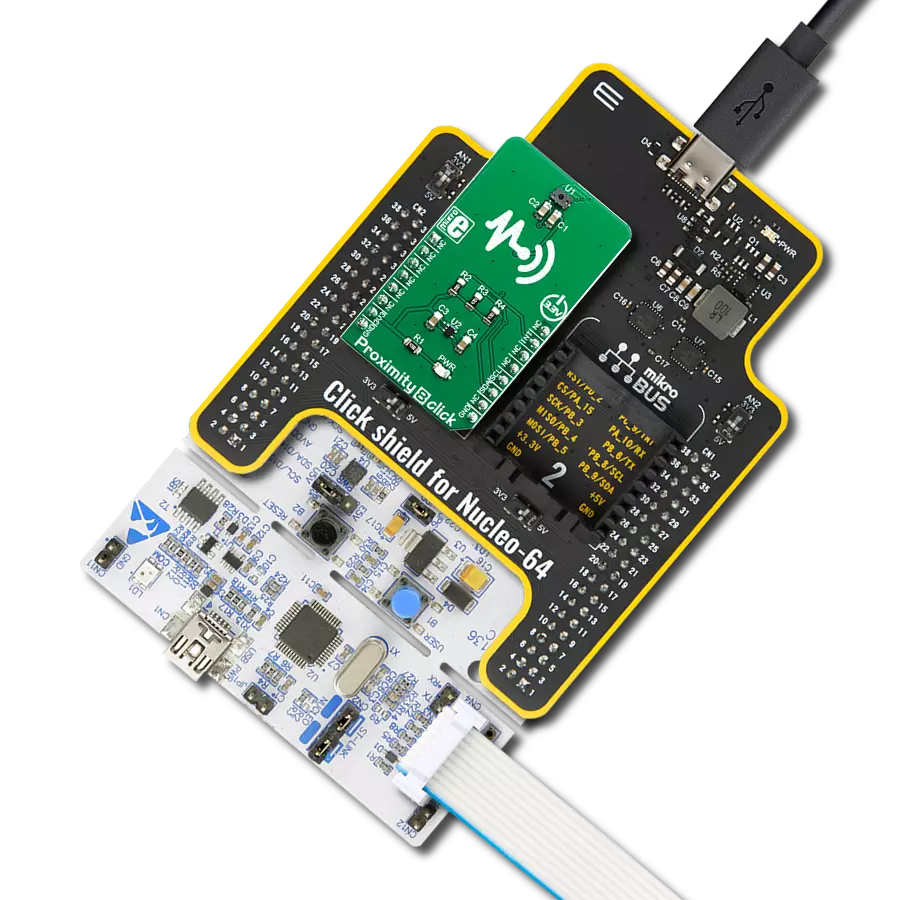
Start by selecting your development board and Click board™. Begin with the UNI-DS v8 as your development board.


Track your results in real time
Application Output
1. Application Output - In Debug mode, the 'Application Output' window enables real-time data monitoring, offering direct insight into execution results. Ensure proper data display by configuring the environment correctly using the provided tutorial.

2. UART Terminal - Use the UART Terminal to monitor data transmission via a USB to UART converter, allowing direct communication between the Click board™ and your development system. Configure the baud rate and other serial settings according to your project's requirements to ensure proper functionality. For step-by-step setup instructions, refer to the provided tutorial.

3. Plot Output - The Plot feature offers a powerful way to visualize real-time sensor data, enabling trend analysis, debugging, and comparison of multiple data points. To set it up correctly, follow the provided tutorial, which includes a step-by-step example of using the Plot feature to display Click board™ readings. To use the Plot feature in your code, use the function: plot(*insert_graph_name*, variable_name);. This is a general format, and it is up to the user to replace 'insert_graph_name' with the actual graph name and 'variable_name' with the parameter to be displayed.

Software Support
Library Description
This library contains API for Proximity 5 Click driver.
Key functions:
proximity5_get_values- Starts the conversion and waits for the interrupt to finish. After the interrupt finishes the proximity data from the proximity registers is returned to a 3 member uint16_t array.proximity5_get_id- Read the ID from the ID register of the sensor.proximity5_read_reg- Generic function for reading both high and low register value and returns those combined values to a 16bit variable.
Open Source
Code example
The complete application code and a ready-to-use project are available through the NECTO Studio Package Manager for direct installation in the NECTO Studio. The application code can also be found on the MIKROE GitHub account.
/*!
 * \file
 * \brief Proximity5 Click example
 *
 * # Description
 * This application enables usage of the proximity and ablient light sensing.
 *
 * The demo application is composed of two sections :
 *
 * ## Application Init
 * Configures the micro controller for communication
 * and initializes the Click board.
 *
 * ## Application Task
 * The proximity data is read from the sensor and it is printed
 * to the UART.
 *
 *
 * \author MikroE Team
 *
 */
// ------------------------------------------------------------------- INCLUDES

#include "board.h"
#include "log.h"
#include "proximity5.h"

// ------------------------------------------------------------------ VARIABLES

static proximity5_t proximity5;
static log_t logger;

// ------------------------------------------------------ APPLICATION FUNCTIONS

void application_init ( void )
{
    log_cfg_t log_cfg;
    proximity5_cfg_t cfg;

    /**
     * Logger initialization.
     * Default baud rate: 115200
     * Default log level: LOG_LEVEL_DEBUG
     * @note If USB_UART_RX and USB_UART_TX
     * are defined as HAL_PIN_NC, you will
     * need to define them manually for log to work.
     * See @b LOG_MAP_USB_UART macro definition for detailed explanation.
     */
    LOG_MAP_USB_UART( log_cfg );
    log_init( &logger, &log_cfg );
    log_info( &logger, "---- Application Init ----" );

    //  Click initialization.

    proximity5_cfg_setup( &cfg );
    PROXIMITY5_MAP_MIKROBUS( cfg, MIKROBUS_1 );
    proximity5_init( &proximity5, &cfg );

    proximity5_default_cfg( &proximity5 );
}

void application_task ( void )
{
    //  Task implementation.

    uint16_t bff[ 4 ];

    proximity5_get_values( &proximity5, bff );

    log_printf( &logger, "PS1 %d  ", bff[ 0 ] );

    log_printf( &logger, "PS2 %d  ", bff[ 1 ] );

    log_printf( &logger, "PS3 %d \r\n\r\n", bff[ 2 ] );

    Delay_ms ( 500 );
}

int main ( void )
{
    /* Do not remove this line or clock might not be set correctly. */
    #ifdef PREINIT_SUPPORTED
    preinit();
    #endif

    application_init( );

    for ( ; ; )
    {
        application_task( );
    }

    return 0;
}


// ------------------------------------------------------------------------ END