Detect the transition points in sinusoidal waveforms with STM32F302VC
Sense the ebb and flow of sinusoidal signals
Published Jul 22, 2025
Click board™
Zero-Cross Click
Dev. board
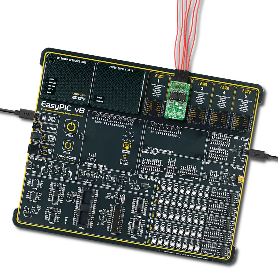
CLICKER 4 for STM32F302VCT6
Compiler
NECTO Studio
MCU
STM32F302VC
Designed for engineers and innovators, our sinusoidal change detection solution ensures that you capture every shift in your signal, empowering you to respond effectively to dynamic changes in your applications.
A
A
Hardware Overview
How does it work?
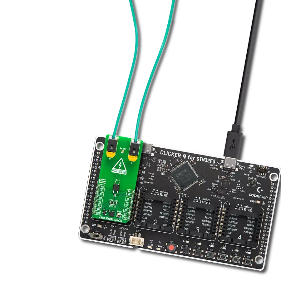
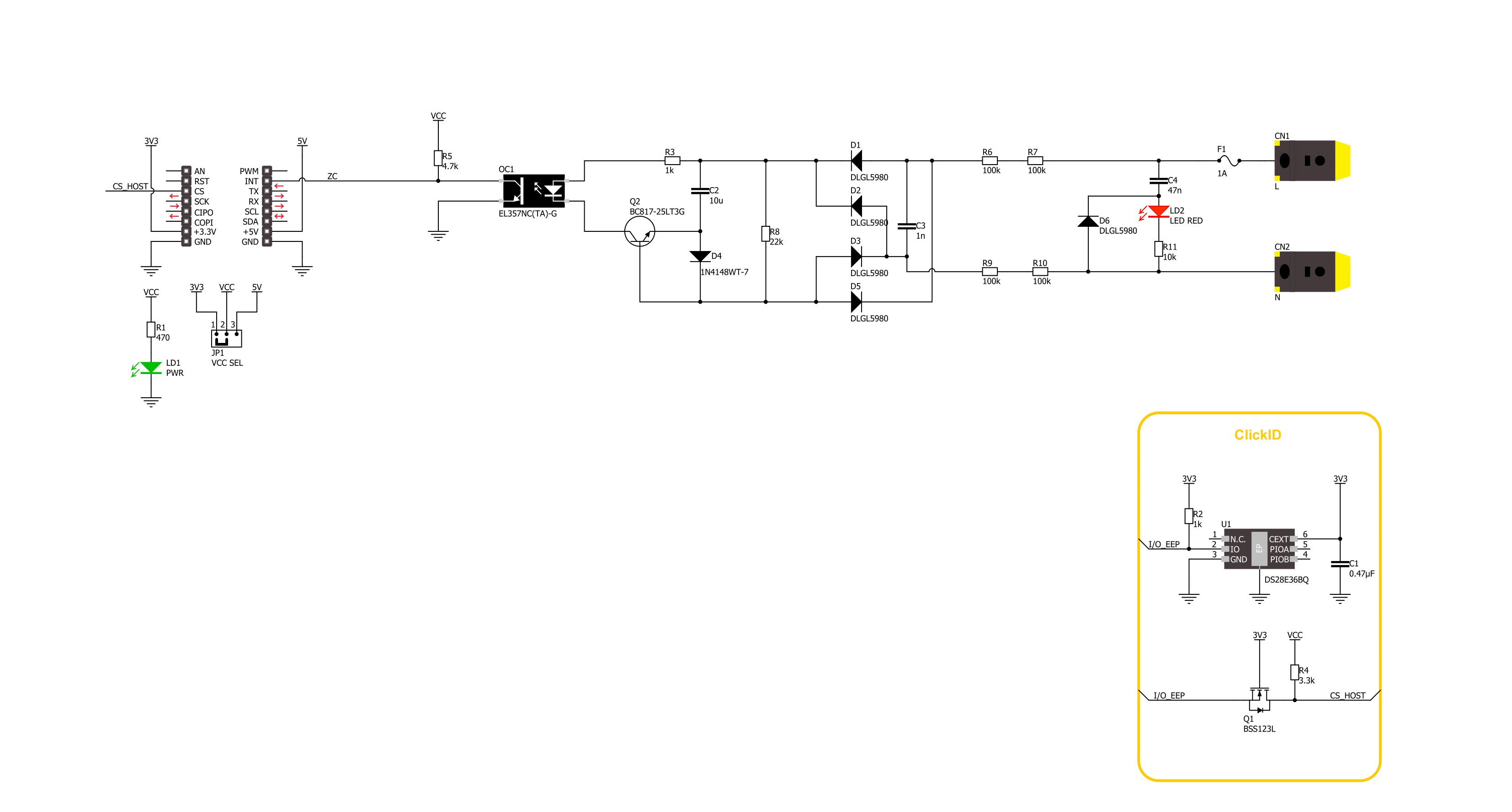
Zero-Cross Click is based on the circuitry that provides Zero Crossing Detection (ZCD). The alternate current can be connected over two block terminals. As it is intended for this Click board™ to work with high voltages, the critical components are placed on the bottom side, but still, take all precautions when working with this Click board™. On the top side is an AC ON LED to present the AC presence visually. All the magic is happening in
the circuitry at the bottom side of this Click board™. The current passes through the Graetz bridge circuitry, consisting of four DLGL5980. The alternate current converts to a direct current, which is necessary for driving an LED in an EL357N-G, a phototransistor photocoupler from Everlight. When activated, the optocoupler sends a LOW logic state to a ZC pin, the pin with which the Zero-Cross Click communicates with the
host MCU. This Click board™ can operate with either 3.3V or 5V logic voltage levels selected via the VCC SEL jumper. This way, both 3.3V and 5V capable MCUs can use the communication lines properly. Also, this Click board™ comes equipped with a library containing easy-to-use functions and an example code that can be used as a reference for further development.

Features overview
Development board
Clicker 4 for STM32F3 is a compact development board designed as a complete solution, you can use it to quickly build your own gadgets with unique functionalities. Featuring a STM32F302VCT6, four mikroBUS™ sockets for Click boards™ connectivity, power managment, and more, it represents a perfect solution for the rapid development of many different types of applications. At its core, there is a STM32F302VCT6 MCU, a powerful microcontroller by STMicroelectronics, based on the high-
performance Arm® Cortex®-M4 32-bit processor core operating at up to 168 MHz frequency. It provides sufficient processing power for the most demanding tasks, allowing Clicker 4 to adapt to any specific application requirements. Besides two 1x20 pin headers, four improved mikroBUS™ sockets represent the most distinctive connectivity feature, allowing access to a huge base of Click boards™, growing on a daily basis. Each section of Clicker 4 is clearly marked, offering an intuitive and clean interface. This makes working with the development
board much simpler and thus, faster. The usability of Clicker 4 doesn’t end with its ability to accelerate the prototyping and application development stages: it is designed as a complete solution which can be implemented directly into any project, with no additional hardware modifications required. Four mounting holes [4.2mm/0.165”] at all four corners allow simple installation by using mounting screws. For most applications, a nice stylish casing is all that is needed to turn the Clicker 4 development board into a fully functional, custom design.

Microcontroller Overview
MCU Card / MCU

Architecture
ARM Cortex-M4
MCU Memory (KB)
256
Silicon Vendor
STMicroelectronics
Pin count
100
RAM (Bytes)
40960
Used MCU Pins
mikroBUS™ mapper
Take a closer look
Click board™ Schematic
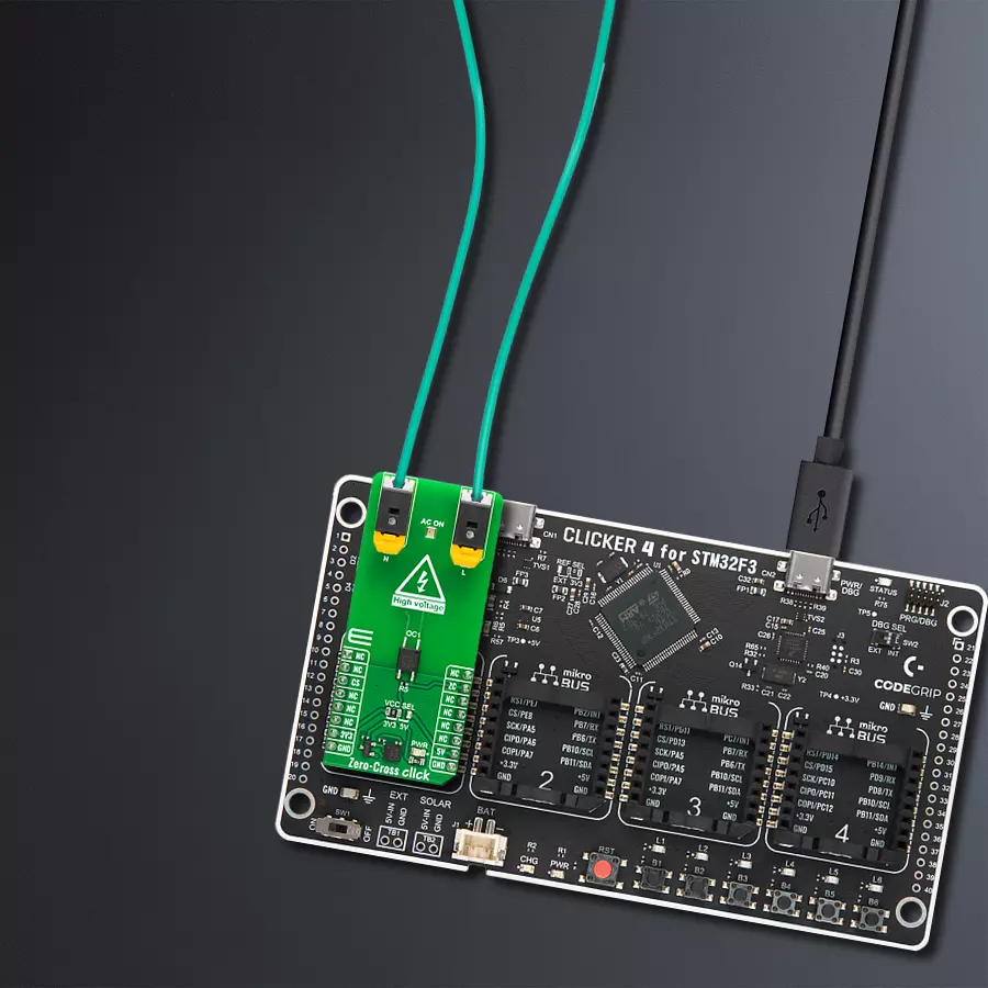
Step by step
Project assembly

Start by selecting your development board and Click board™. Begin with the CLICKER 4 for STM32F302VCT6 as your development board.


Track your results in real time
Application Output
1. Application Output - In Debug mode, the 'Application Output' window enables real-time data monitoring, offering direct insight into execution results. Ensure proper data display by configuring the environment correctly using the provided tutorial.

2. UART Terminal - Use the UART Terminal to monitor data transmission via a USB to UART converter, allowing direct communication between the Click board™ and your development system. Configure the baud rate and other serial settings according to your project's requirements to ensure proper functionality. For step-by-step setup instructions, refer to the provided tutorial.

3. Plot Output - The Plot feature offers a powerful way to visualize real-time sensor data, enabling trend analysis, debugging, and comparison of multiple data points. To set it up correctly, follow the provided tutorial, which includes a step-by-step example of using the Plot feature to display Click board™ readings. To use the Plot feature in your code, use the function: plot(*insert_graph_name*, variable_name);. This is a general format, and it is up to the user to replace 'insert_graph_name' with the actual graph name and 'variable_name' with the parameter to be displayed.

Software Support
Library Description
This library contains API for Zero-Cross Click driver.
Key functions:
zerocross_pin_read- Zero-Cross pin reading function.zerocross_get_freq- Zero-Cross frequency reading function.
Open Source
Code example
The complete application code and a ready-to-use project are available through the NECTO Studio Package Manager for direct installation in the NECTO Studio. The application code can also be found on the MIKROE GitHub account.
/*!
 * @file main.c
 * @brief Zero-Cross Click Example.
 *
 * # Description
 * This example demonstrates the use of the Zero-Cross Click board.
 *
 * The demo application is composed of two sections :
 *
 * ## Application Init
 * Initialization of the log UART and basic Click initialisation.
 *
 * ## Application Task
 * Reading frequency value approximately once every second.
 *
 * @author Stefan Ilic
 *
 */

#include "board.h"
#include "log.h"
#include "zerocross.h"

static zerocross_t zerocross;   /**< Zero-Cross Click driver object. */
static log_t logger;    /**< Logger object. */

void application_init ( void )
{
    log_cfg_t log_cfg;  /**< Logger config object. */
    zerocross_cfg_t zerocross_cfg;  /**< Click config object. */

    /**
     * Logger initialization.
     * Default baud rate: 115200
     * Default log level: LOG_LEVEL_DEBUG
     * @note If USB_UART_RX and USB_UART_TX
     * are defined as HAL_PIN_NC, you will
     * need to define them manually for log to work.
     * See @b LOG_MAP_USB_UART macro definition for detailed explanation.
     */
    LOG_MAP_USB_UART( log_cfg );
    log_init( &logger, &log_cfg );
    log_info( &logger, " Application Init " );

    // Click initialization.
    zerocross_cfg_setup( &zerocross_cfg );
    ZEROCROSS_MAP_MIKROBUS( zerocross_cfg, MIKROBUS_1 );
    if ( DIGITAL_OUT_UNSUPPORTED_PIN == zerocross_init( &zerocross, &zerocross_cfg ) )
    {
        log_error( &logger, " Communication init." );
        for ( ; ; );
    }

    log_info( &logger, " Application Task " );
}

void application_task ( void )
{
    float freq_val = 0;
    zerocross_get_freq( &zerocross, &freq_val );
    log_printf( &logger, " Freq %.2f Hz \n\r", freq_val );
}

int main ( void )
{
    /* Do not remove this line or clock might not be set correctly. */
    #ifdef PREINIT_SUPPORTED
    preinit();
    #endif

    application_init( );

    for ( ; ; )
    {
        application_task( );
    }

    return 0;
}

// ------------------------------------------------------------------------ END
Additional Support
Resources
Category:Optocoupler