ECG at your fingertips with ADS1194 and PIC18F46K22
Unveiling vital rhythms
Published Jul 28, 2023
Click board™
ECG 2 Click
Dev. board
EasyPIC v7a
Compiler
NECTO Studio
MCU
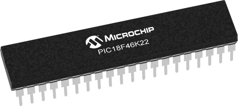
PIC18F46K22
Experience the power of real-time ECG monitoring that provides instant and accurate insights into heart health
A
A
Hardware Overview
How does it work?
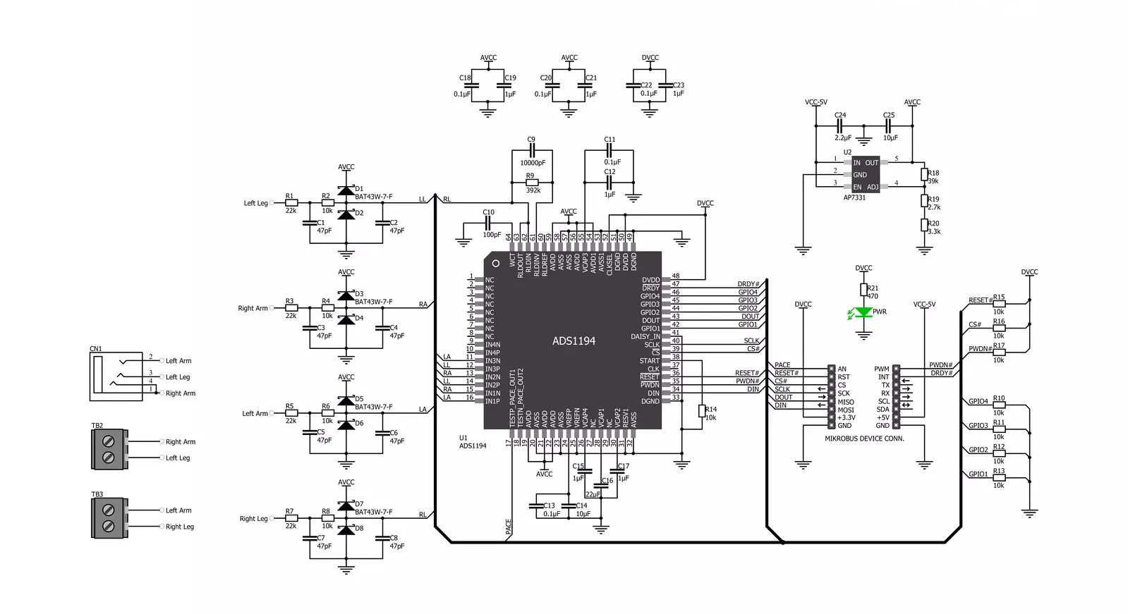
ECG 2 Click is based on the ADS1194, a low-power, 8-channel, 16-bit analog front-end for biopotential measurements from Texas Instruments. The ADS1194 is a multichannel simultaneous sampling delta-sigma analog-to-digital converter with a built-in programmable gain amplifier, internal reference, and onboard oscillator. It has a flexible input multiplexer per channel that can be independently connected to the internally generated signals for test, temperature, and lead-off detection. This ADC can sample data in a range of 125sps up to 8ksps data rates, with a programmable gain in 1, 2, 3, 4, 6, 8, or 12 steps. In addition, the ECG 2 Click features the built-in right leg drive amplifier, lead-off detection, WCT, test signals, pace detection channel selection, and more. The ECG 2 Click can work in several modes. The Continuous mode is ideal for applications that require a fixed stream of conversion results. The Single-Shot conversion mode is provided for applications that require a non-standard or non-continuous data rate. An onboard 3.5mm phone
jack is used to connect cables/electrodes to the Click board™. The electrode collects voltage from the skin, after which the signal is amplified, filtered, and sent to the host MCU over the mikroBUS™ socket. The three electrodes should be placed on the left arm, right arm, and the left side of the abdomen (below the heart), on the left leg. In addition to the phone jack, the ECG 2 Click includes screw terminals for a 4-wire measurement. ECG 2 click can also be connected by four electrodes placed on both arms and legs. The final measurement results can be displayed as an Electrocardiogram using a free app, the MikroPlot, a free data visualization tool (Windows). It's a simple tool to help you visualize sensor data recorded over time, suitable for biosignals (ECG, EEG, EMG) and environmental data logging (temperature, humidity, and more). The graph is generated from data sent from the MCU (ADC values from ECG 2 click input + timestamp). The app can receive data sets from a microcontroller through a USB UART connection. ECG 2 Click uses
a standard 4-Wire SPI serial interface to communicate with the host MCU. The data-ready output is used as a status signal to indicate when data are ready, where the DRD pin will go LOW if new data are available. In addition, other pins meet the ECG 2 Click's functionalities. The ADS1194 can be reset over the RST pin with an active LOW logic state, while it can be powered down with an active LOW on the PWD pin. The host MCU can be used to detect the presence of the pulse by bringing out the output of the PGA at the PAC pin (TEST PACE OUT1). This Click board™ can be operated only with a 3.3V logic voltage level while it uses a 5V for analog power supply via LDO (3V stabilized). The board must perform appropriate logic voltage level conversion before using MCUs with different logic levels. However, the Click board™ comes equipped with a library containing functions and an example code that can be used, as a reference, for further development.

Features overview
Development board
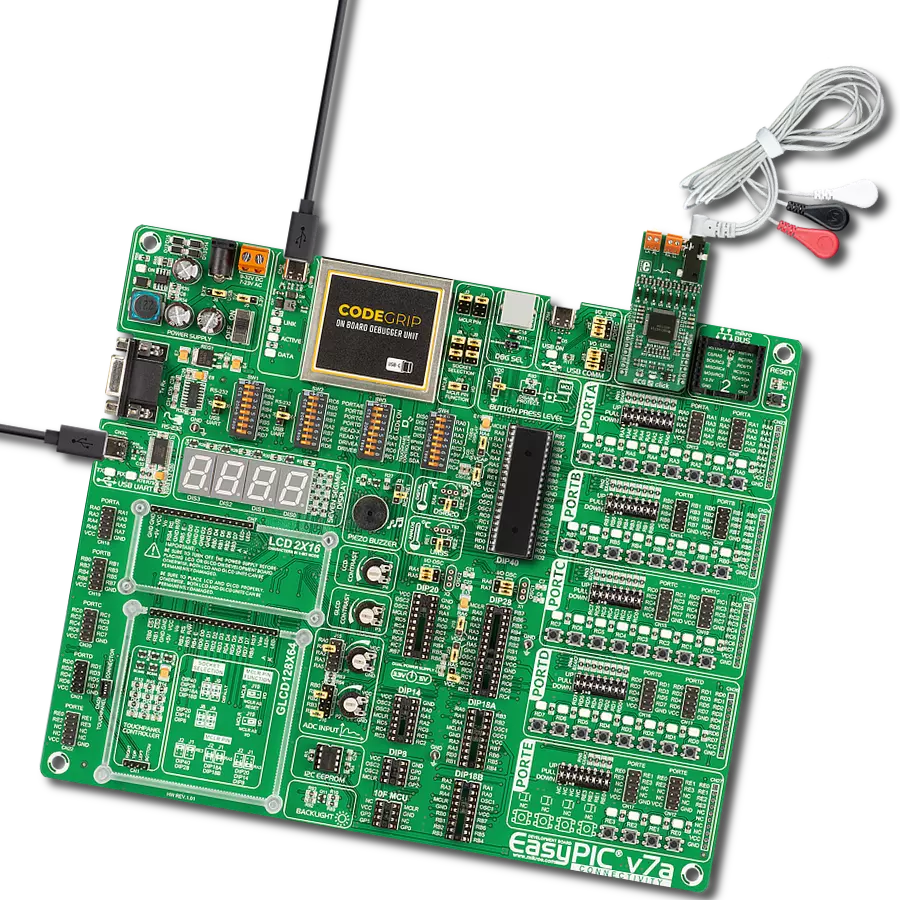
EasyPIC v7a is the seventh generation of PIC development boards specially designed for the needs of rapid development of embedded applications. It supports a wide range of 8-bit PIC microcontrollers from Microchip and has a broad set of unique functions, such as the first-ever embedded debugger/programmer over USB-C. The development board is well organized and designed so that the end-user has all the necessary elements in one place, such as switches, buttons, indicators, connectors, and others. With four different connectors for each port, EasyPIC v7a allows you to connect accessory boards, sensors, and custom electronics more efficiently than ever. Each part of the EasyPIC v7a development board
contains the components necessary for the most efficient operation of the same board. In addition to the advanced integrated CODEGRIP programmer/debugger module, which offers many valuable programming/debugging options and seamless integration with the Mikroe software environment, the board also includes a clean and regulated power supply module for the development board. It can use various external power sources, including an external 12V power supply, 7-23V AC or 9-32V DC via DC connector/screw terminals, and a power source via the USB Type-C (USB-C) connector. Communication options such as USB-UART and RS-232 are also included, alongside the well-
established mikroBUS™ standard, three display options (7-segment, graphical, and character-based LCD), and several different DIP sockets. These sockets cover a wide range of 8-bit PIC MCUs, from PIC10F, PIC12F, PIC16F, PIC16Enh, PIC18F, PIC18FJ, and PIC18FK families. EasyPIC v7a is an integral part of the Mikroe ecosystem for rapid development. Natively supported by Mikroe software tools, it covers many aspects of prototyping and development thanks to a considerable number of different Click boards™ (over a thousand boards), the number of which is growing every day.

Microcontroller Overview
MCU Card / MCU
Architecture
PIC
MCU Memory (KB)
64
Silicon Vendor
Microchip
Pin count
40
RAM (Bytes)
3896
You complete me!
Accessories
3-wire ECG/EMG cable comes with a convenient 3.5mm phone jack, and it is designed for electrocardiogram recording. This 1m cable is a practical companion for medical professionals and enthusiasts. To complement this cable, you can also use single-use adhesive ECG/EMG electrodes measuring 48x34mm, each equipped with an ECG/EMG cable stud adapter. These electrodes ensure a seamless experience when paired with our ECG/EMG cable and guarantee reliable ECG/EMG signal transmission for comprehensive cardiac monitoring. Trust in the accuracy and convenience of this setup to effortlessly record electrocardiograms and electromyograms with confidence.

Used MCU Pins
mikroBUS™ mapper
Take a closer look
Click board™ Schematic
Step by step
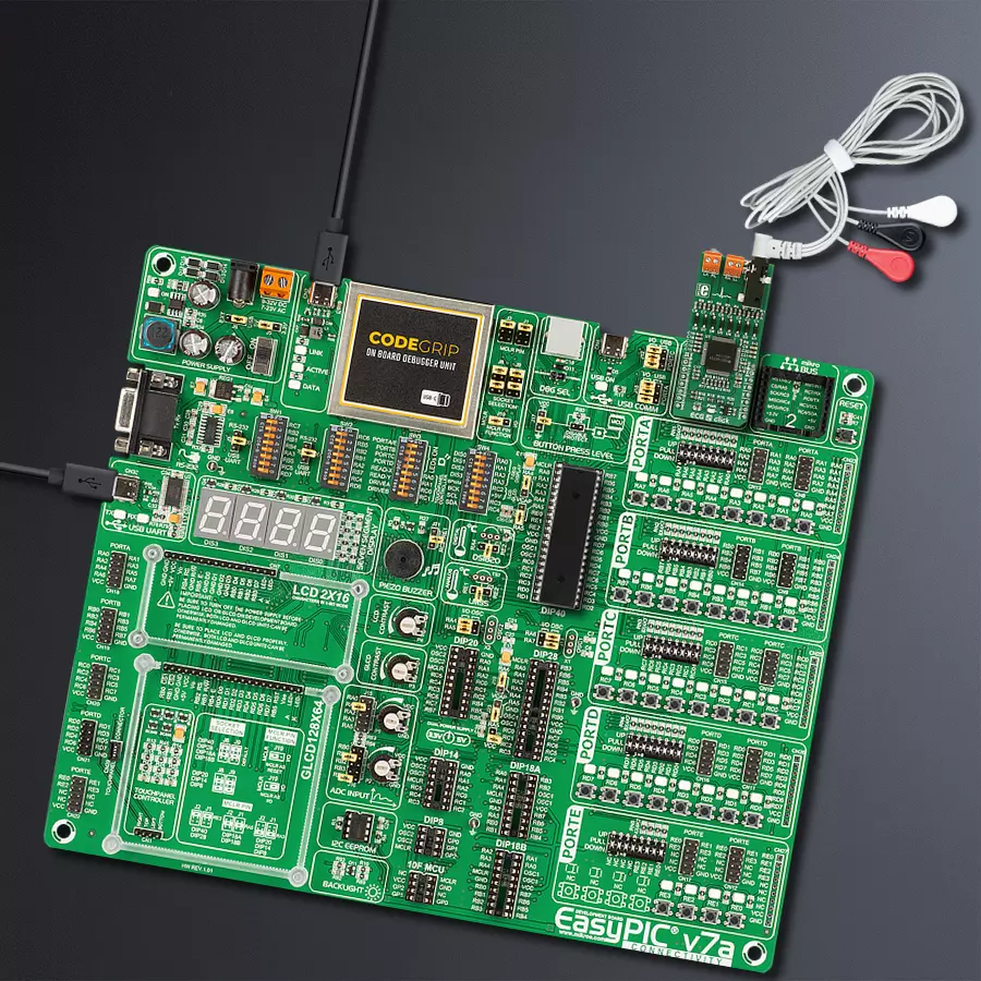
Project assembly

Start by selecting your development board and Click board™. Begin with the EasyPIC v7a as your development board.


Software Support
Library Description
This library contains API for ECG 2 Click driver.
Key functions:
ecg2_read_an_pin_value- ECG 2 read AN pin value functionecg2_send_command- ECG 2 send command functionecg2_read_channel_data- ECG 2 read data channel function
Open Source
Code example
The complete application code and a ready-to-use project are available through the NECTO Studio Package Manager for direct installation in the NECTO Studio. The application code can also be found on the MIKROE GitHub account.
/*!
 * @file main.c
 * @brief ECG2 Click example
 *
 * # Description
 * This is an example that demonstrates the use of the ECG 2 Click board.
 *
 * The demo application is composed of two sections :
 *
 * ## Application Init
 * Initializes SPI and UART communication, configures INT pin as INPUT, RST pin as OUTPUT, CS pin as
 * OUTPUT and PWM pin as OUTPUT. Initializes SPI driver, initializes ECG2 Click, sends START and
 * RDATAC opcodes.
 *
 * ## Application Task
 * Captures readings from channel and plots data to serial plotter.
 *
 * @author Stefan Ilic
 *
 */

#include "board.h"
#include "log.h"
#include "ecg2.h"

static ecg2_t ecg2;
static log_t logger;
uint32_t time;

void application_init ( void )
{
    log_cfg_t log_cfg;  /**< Logger config object. */
    ecg2_cfg_t ecg2_cfg;  /**< Click config object. */

    /**
     * Logger initialization.
     * Default baud rate: 115200
     * Default log level: LOG_LEVEL_DEBUG
     * @note If USB_UART_RX and USB_UART_TX
     * are defined as HAL_PIN_NC, you will
     * need to define them manually for log to work.
     * See @b LOG_MAP_USB_UART macro definition for detailed explanation.
     */
    LOG_MAP_USB_UART( log_cfg );
    log_init( &logger, &log_cfg );
    log_info( &logger, " Application Init " );

    // Click initialization.
    ecg2_cfg_setup( &ecg2_cfg );
    ECG2_MAP_MIKROBUS( ecg2_cfg, MIKROBUS_1 );
    if ( SPI_MASTER_ERROR == ecg2_init( &ecg2, &ecg2_cfg ) )
    {
        log_error( &logger, " Communication init." );
        for ( ; ; );
    }
    SET_SPI_DATA_SAMPLE_EDGE;

    if ( ECG2_ERROR == ecg2_default_cfg ( &ecg2 ) )
    {
        log_error( &logger, " Default configuration." );
        for ( ; ; );
    }
    Delay_ms ( 100 );
    ecg2_send_command( &ecg2, ECG2_START_CONVERSION );
    Delay_ms ( 100 );
    ecg2_send_command( &ecg2, ECG2_ENABLE_READ_DATA_CONT_MODE );
    Delay_ms ( 100 );

    log_info( &logger, " Application Task " );
    Delay_ms ( 100 );
}

void application_task ( void )
{
    uint16_t ecg_an = 0;
    ecg2_read_channel_data( &ecg2, 5, &ecg_an );
    log_printf( &logger, " %.6u, %.8lu \r\n", ecg_an, time );
    time += 5;
    Delay_ms ( 5 );
}

int main ( void )
{
    /* Do not remove this line or clock might not be set correctly. */
    #ifdef PREINIT_SUPPORTED
    preinit();
    #endif

    application_init( );

    for ( ; ; )
    {
        application_task( );
    }

    return 0;
}

// ------------------------------------------------------------------------ END


