Ensure each move is spot on with AEDR-8300 and PIC18F45K22 for precise positioning control
See every spin: Optical encoder - your simple motion counter

Published Sep 22, 2023
Click board™
Opto Encoder 2 Click
Dev. board
EasyPIC v7a
Compiler
NECTO Studio
MCU
PIC18F45K22
Count on our optical encoder for accurate, reliable, and responsive motion sensing
A
A
Hardware Overview
How does it work?
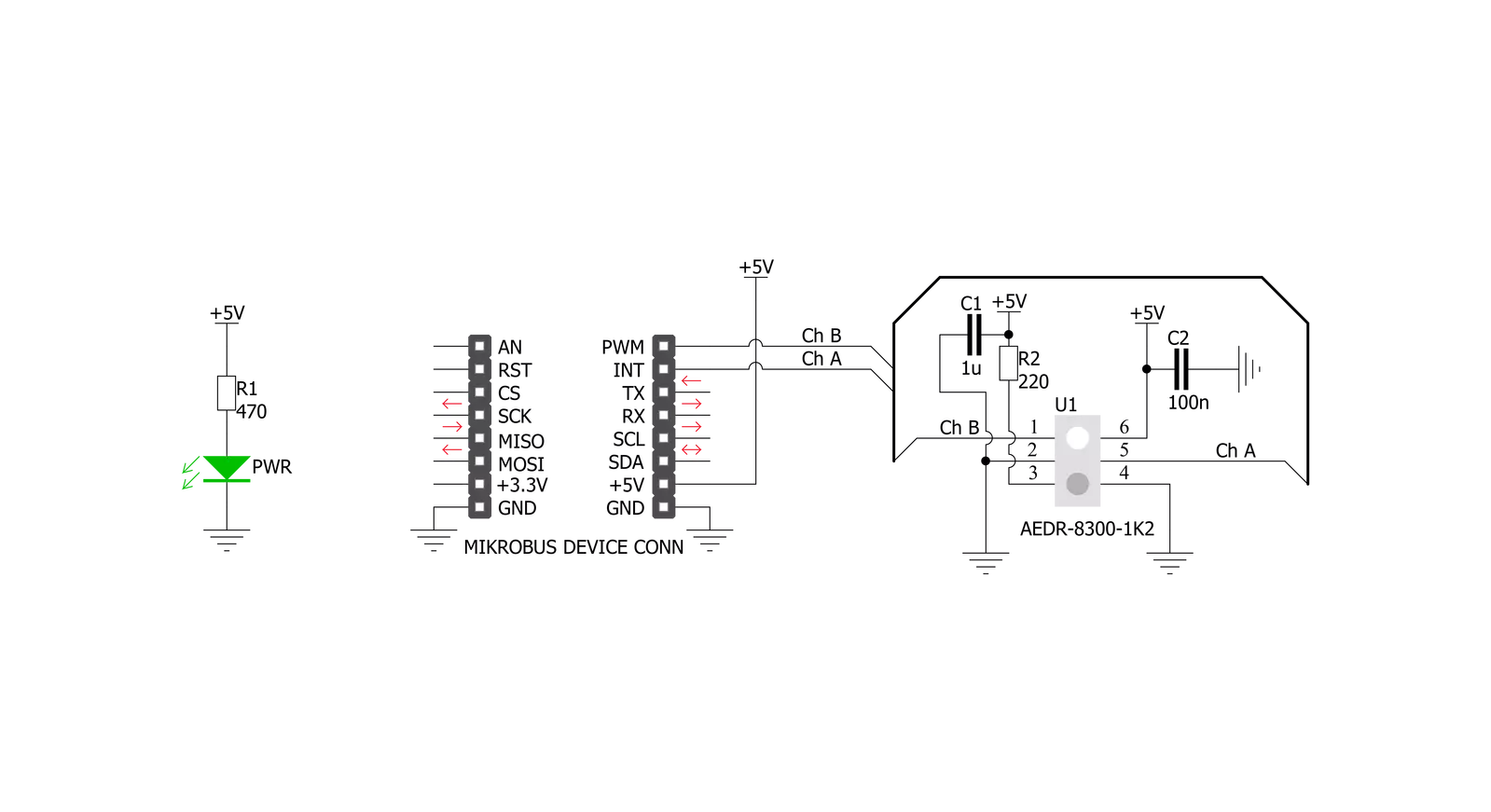
Opto Encoder 2 Click is based on the AEDR-8300, reflective Surface Mount Optical Encoder from Avago Technologies. This sensor combines an emitter and a detector in a single surface mount leadless package. the AEDR-8300 consists of three major components: a light emitting diode (LED) light source, a detector IC consisting photodiodes and lens to focus light beam from the emitter as well as light falling on the detector. The operation of the encoder is based on the principle of optics where the detector photodiodes sense the absence and presence of light. In this case, the rotary/linear motion of an object being monitored is converted to equivalent light pattern via the use of codewheel/codestrip. Opto Encoder 2 Click offers options of either single channel or two-channel quadrature digital outputs. Being TTL compatible, the outputs of the AEDR-8300 series
can be interfaced directly with MCU. Hence the Opto Encoder 2 click provides great design-in flexibility and easy integration into existing systems. A and B pins are routed to the routed to the mikroBUS™ PWM and INT pins, thus providing the quadrature digital signal. Signal encoding itself is done by the host MCU. Having two optical sensing channels, Opto Encoder 2 click has the ability of both speed and direction encoding. The most common usage is encoding of the step motor position: a cylinder with slits is physically mounted above the sensor so that the LED can illuminate the photodiodes only when light hits the reflective surface of the codewheel. By rotating this cylinder, the light beam will be blocked periodically. The single sensor output will be a pulse train, while the cylinder is rotating. Having two photo sensors physically distanced by
a small amount, allows the pulse signal of the first sensor to be either delayed or expedited with respect to the pulse on the second sensor, depending on the rotational direction. Since the sensors recomended operating voltage is 5V, the Opto Encoder 2 click uses the 5V rail for power supply. The other pins it utilizes are the, before mentioned, Interrupt and PWM pins on mikroBUS™ socket. This click also has a Power LED indicator. This Click board™ can be operated only with a 5V logic voltage level. The board must perform appropriate logic voltage level conversion before using MCUs with different logic levels. Also, it comes equipped with a library containing functions and an example code that can be used as a reference for further development.


Features overview
Development board
EasyPIC v7a is the seventh generation of PIC development boards specially designed for the needs of rapid development of embedded applications. It supports a wide range of 8-bit PIC microcontrollers from Microchip and has a broad set of unique functions, such as the first-ever embedded debugger/programmer over USB-C. The development board is well organized and designed so that the end-user has all the necessary elements in one place, such as switches, buttons, indicators, connectors, and others. With four different connectors for each port, EasyPIC v7a allows you to connect accessory boards, sensors, and custom electronics more efficiently than ever. Each part of the EasyPIC v7a development board
contains the components necessary for the most efficient operation of the same board. In addition to the advanced integrated CODEGRIP programmer/debugger module, which offers many valuable programming/debugging options and seamless integration with the Mikroe software environment, the board also includes a clean and regulated power supply module for the development board. It can use various external power sources, including an external 12V power supply, 7-23V AC or 9-32V DC via DC connector/screw terminals, and a power source via the USB Type-C (USB-C) connector. Communication options such as USB-UART and RS-232 are also included, alongside the well-
established mikroBUS™ standard, three display options (7-segment, graphical, and character-based LCD), and several different DIP sockets. These sockets cover a wide range of 8-bit PIC MCUs, from PIC10F, PIC12F, PIC16F, PIC16Enh, PIC18F, PIC18FJ, and PIC18FK families. EasyPIC v7a is an integral part of the Mikroe ecosystem for rapid development. Natively supported by Mikroe software tools, it covers many aspects of prototyping and development thanks to a considerable number of different Click boards™ (over a thousand boards), the number of which is growing every day.

Microcontroller Overview
MCU Card / MCU
Architecture
PIC
MCU Memory (KB)
32
Silicon Vendor
Microchip
Pin count
40
RAM (Bytes)
1536
Used MCU Pins
mikroBUS™ mapper
Take a closer look
Click board™ Schematic
Step by step
Project assembly

Start by selecting your development board and Click board™. Begin with the EasyPIC v7a as your development board.


Track your results in real time
Application Output
1. Application Output - In Debug mode, the 'Application Output' window enables real-time data monitoring, offering direct insight into execution results. Ensure proper data display by configuring the environment correctly using the provided tutorial.

2. UART Terminal - Use the UART Terminal to monitor data transmission via a USB to UART converter, allowing direct communication between the Click board™ and your development system. Configure the baud rate and other serial settings according to your project's requirements to ensure proper functionality. For step-by-step setup instructions, refer to the provided tutorial.

3. Plot Output - The Plot feature offers a powerful way to visualize real-time sensor data, enabling trend analysis, debugging, and comparison of multiple data points. To set it up correctly, follow the provided tutorial, which includes a step-by-step example of using the Plot feature to display Click board™ readings. To use the Plot feature in your code, use the function: plot(*insert_graph_name*, variable_name);. This is a general format, and it is up to the user to replace 'insert_graph_name' with the actual graph name and 'variable_name' with the parameter to be displayed.

Software Support
Library Description
This library contains API for Opto Encoder 2 Click driver.
Key functions:
optoencoder2_pwm_get- Getting PWM pin stateoptoencoder2_int_get- Getting INT pin stateoptoencoder2_get_position- Getting encoder position
Open Source
Code example
The complete application code and a ready-to-use project are available through the NECTO Studio Package Manager for direct installation in the NECTO Studio. The application code can also be found on the MIKROE GitHub account.
/*!
 * \file
 * \brief Opto Encoder 2 Click example
 *
 * # Description
 * This application is used to encode motion or rotation.
 *
 * The demo application is composed of two sections :
 *
 * ## Application Init
 * Initializes GPIO driver and resets encoder counter to 0 (zero).
 *
 * ## Application Task
 * If motion is detected - encoder increments or decrements position
 * on each rising edge on Channel A (INT pin) and logs encoder position.
 *
 * \author MikroE Team
 *
 */
// ------------------------------------------------------------------- INCLUDES

#include "board.h"
#include "log.h"
#include "optoencoder2.h"

// ------------------------------------------------------------------ VARIABLES

static optoencoder2_t optoencoder2;
static log_t logger;

// ------------------------------------------------------ APPLICATION FUNCTIONS

void application_init ( void )
{
    log_cfg_t log_cfg;
    optoencoder2_cfg_t cfg;

    /**
     * Logger initialization.
     * Default baud rate: 115200
     * Default log level: LOG_LEVEL_DEBUG
     * @note If USB_UART_RX and USB_UART_TX
     * are defined as HAL_PIN_NC, you will
     * need to define them manually for log to work.
     * See @b LOG_MAP_USB_UART macro definition for detailed explanation.
     */
    LOG_MAP_USB_UART( log_cfg );
    log_init( &logger, &log_cfg );
    log_info(&logger, "---- Application Init ----");

    //  Click initialization.
    optoencoder2_cfg_setup( &cfg );
    OPTOENCODER2_MAP_MIKROBUS( cfg, MIKROBUS_1 );
    optoencoder2_init( &optoencoder2, &cfg );

    optoencoder2_zero_counter( &optoencoder2 );
}

void application_task ( )
{
    int32_t encoder_position = 0;
    uint8_t stop_flag = 0;

    stop_flag = optoencoder2_isr( &optoencoder2, 100 );
    encoder_position = optoencoder2_get_position( &optoencoder2 );

    if ( stop_flag == 0 )
    {
        log_printf( &logger, "Position: %ld \r\n", encoder_position );
    }
}

int main ( void )
{
    /* Do not remove this line or clock might not be set correctly. */
    #ifdef PREINIT_SUPPORTED
    preinit();
    #endif

    application_init( );

    for ( ; ; )
    {
        application_task( );
    }

    return 0;
}

// ------------------------------------------------------------------------ END


