Simplify temperature tracking for your convenience and peace of mind using TMP116 and PIC18F47K40
Hot data - cool solutions

Published Nov 07, 2023
Click board™
Temp-Log 2 Click
Dev. board
EasyPIC v7a
Compiler
NECTO Studio
MCU
PIC18F47K40
We go beyond temperature measurement with added EEPROM memory, ensuring your data is secure and accessible whenever you need it
A
A
Hardware Overview
How does it work?
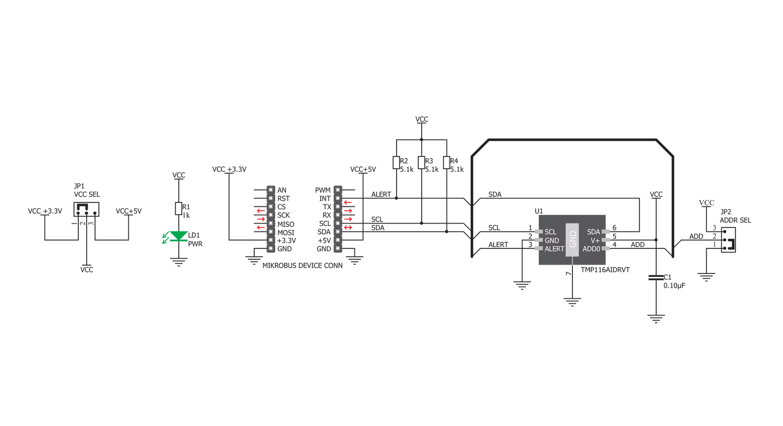
Temp-Log 2 Click is based on the TMP116, high-accuracy, low-power, digital temperature sensor, from Texas Instruments. The TMP116 utilizes a diode type temperature sensor with an internal sigma-delta 16bit ADC for the temperature measurement and conversion. The device can work in several operating modes that affect the power consumption, as well as the measurement accuracy. Equipped with 16bit ADC, TMP116 provides measurement step of 0.0078125°C. The TMP116 sensor uses the I2C bus for the communication with the MCU. This sensor has six config/data registers, which are used to access all the functions of this device. It also has four additional registers for storing user-specific data in the non-volatile memory area (EEPROM). After initializing the I2C communication with the START condition from the master, a valid device address is expected. This thermal sensor uses the 100100A binary value as the 7bit I2C address, where “A” corresponds to the logical state of the ADDR0 pin. This pin can be set to a HIGH or a LOW logic state by switching the position of the onboard SMD jumper, labeled as ADDR SEL. The TMP116 sensor is made with the power saving in mind. When the Shutdown mode is engaged, the power consumption is minimal and most of the device sections are not consuming any power. One Shot mode allows to wake up the device, take one measurement, update the registers, and revert to the Shutdown mode again. This allows for a minimum power consumption. To allow One Shot mode, the device needs to be put into the
Shutdown mode first. The most power is consumed by the Continuous mode. This mode allows setting the integration and the standby time. Integration time actively burst-samples the thermal data, reducing the noise error by averaging the result. Allowing longer stand-by duration prevents too much power consumption, as well as the additional self-heating of the sensor IC which would affect the accuracy of the measurement. The 16bit Configuration register is used to configure all the working parameters of the sensor: working mode (one-shot mode, continuous conversion mode, and shutdown mode), measurement conversion and integration parameters, the polarity of the ALERT pin, DATA_RDY status, non-volatile memory busy status, and so on. There is also a copy of this register in the non-volatile memory, which can be independently changed. After the power on, the content of the non-volatile Configuration register will be copied to its volatile counterpart allowing settings retention, even after power down. To write data to the non-volatile memory locations, it is necessary to first unlock the EUN lock bit in the EEPROM Unlock register. After the EEPROM unlock, it is possible to write in the EEPROM locations. Four general purpose EEPROM register locations can be used for storing any type of data. Writing data to the configuration registers will mirror the data to the respective EEPROM locations. EEPROM Unlock register also contains the EEPROM_Busy bit, which indicates the readiness of the EEPROM. If this bit is 0, the
writing to EEPROM is possible. This bit mirrors the same bit in the Configuration register. There are two more 16bit registers used to set the high and low temperature threshold, which also have their non-volatile copies. Depending on the ALERT mode bit in the Configuration register, the temperature threshold values in these registers will be used to trigger an event on the ALERT pin, routed to the mikroBUS™ INT pin. This pin is pulled HIGH on this Click board™ by a resistor, so it is a good idea to configure it as active LOW, by using the polarity bit in the Configuration register. The TMP116 device contains a register with the unique device ID, which is factory programmed to read only locations. Additionally, the general purpose EEPROM registers are pre-programmed with one more unique ID, which allows NIST traceability. The TMP116 units are 100% tested on a production setup that is NIST traceable and verified with equipment that is calibrated to ISO/IEC 17025 accredited standards. If the NIST traceability is not required, general purpose EEPROM registers can be freely overwritten. MikroElektronika provides libraries and functions which simplify working with this device. For more detailed information on the functionality of this device, TMP116 datasheet can be consulted. Temp-Log 2 click is capable of working with both 3.3V and 5V systems. The desired operational voltage can be selected by the VCC SEL SMD jumper. SCL and SDA lines are both pulled HIGH by the onboard resistors, so the Temp-Log 2 click is ready to be used right out of the box.

Features overview
Development board
EasyPIC v7a is the seventh generation of PIC development boards specially designed for the needs of rapid development of embedded applications. It supports a wide range of 8-bit PIC microcontrollers from Microchip and has a broad set of unique functions, such as the first-ever embedded debugger/programmer over USB-C. The development board is well organized and designed so that the end-user has all the necessary elements in one place, such as switches, buttons, indicators, connectors, and others. With four different connectors for each port, EasyPIC v7a allows you to connect accessory boards, sensors, and custom electronics more efficiently than ever. Each part of the EasyPIC v7a development board
contains the components necessary for the most efficient operation of the same board. In addition to the advanced integrated CODEGRIP programmer/debugger module, which offers many valuable programming/debugging options and seamless integration with the Mikroe software environment, the board also includes a clean and regulated power supply module for the development board. It can use various external power sources, including an external 12V power supply, 7-23V AC or 9-32V DC via DC connector/screw terminals, and a power source via the USB Type-C (USB-C) connector. Communication options such as USB-UART and RS-232 are also included, alongside the well-
established mikroBUS™ standard, three display options (7-segment, graphical, and character-based LCD), and several different DIP sockets. These sockets cover a wide range of 8-bit PIC MCUs, from PIC10F, PIC12F, PIC16F, PIC16Enh, PIC18F, PIC18FJ, and PIC18FK families. EasyPIC v7a is an integral part of the Mikroe ecosystem for rapid development. Natively supported by Mikroe software tools, it covers many aspects of prototyping and development thanks to a considerable number of different Click boards™ (over a thousand boards), the number of which is growing every day.

Microcontroller Overview
MCU Card / MCU
Architecture
PIC
MCU Memory (KB)
128
Silicon Vendor
Microchip
Pin count
40
RAM (Bytes)
3728
Used MCU Pins
mikroBUS™ mapper
Take a closer look
Click board™ Schematic
Step by step
Project assembly

Start by selecting your development board and Click board™. Begin with the EasyPIC v7a as your development board.


Track your results in real time
Application Output
1. Application Output - In Debug mode, the 'Application Output' window enables real-time data monitoring, offering direct insight into execution results. Ensure proper data display by configuring the environment correctly using the provided tutorial.

2. UART Terminal - Use the UART Terminal to monitor data transmission via a USB to UART converter, allowing direct communication between the Click board™ and your development system. Configure the baud rate and other serial settings according to your project's requirements to ensure proper functionality. For step-by-step setup instructions, refer to the provided tutorial.

3. Plot Output - The Plot feature offers a powerful way to visualize real-time sensor data, enabling trend analysis, debugging, and comparison of multiple data points. To set it up correctly, follow the provided tutorial, which includes a step-by-step example of using the Plot feature to display Click board™ readings. To use the Plot feature in your code, use the function: plot(*insert_graph_name*, variable_name);. This is a general format, and it is up to the user to replace 'insert_graph_name' with the actual graph name and 'variable_name' with the parameter to be displayed.

Software Support
Library Description
This library contains API for Temp-Log 2 Click driver.
Key functions:
templog2_write_reg- Write Register function.templog2_read_reg- Read Register function.templog2_read_temp- Read Temperature function.
Open Source
Code example
The complete application code and a ready-to-use project are available through the NECTO Studio Package Manager for direct installation in the NECTO Studio. The application code can also be found on the MIKROE GitHub account.
/*!
 * \file main.c
 * \brief Temp-Log 2 Click example
 *
 * # Description
 * This example demonstrates the use of the Temp-Log 2 Click board.
 *
 * The demo application is composed of two sections :
 *
 * ## Application Init
 * Initializes peripherals and pins.
 * Initializes I2C driver and performs device configuration.
 * Sets total active conversion time to 250 ms and 8 average samples.
 * Also sets Shutdown Mode as default mode, and after device reset puts device
 * in Continuous Conversion Mode.
 * High limit status will be set when temperature cross over the determined
 * high limit temperature value.
 * Low limit status will be set when temperature falls below the determined
 * low limit temperature value.
 *
 * ## Application Task
 * Reads temperature value calculated to Celsius degrees.
 *
 * \author Nemanja Medakovic
 *
 */
// ------------------------------------------------------------------- INCLUDES

#include "board.h"
#include "log.h"
#include "templog2.h"


// ------------------------------------------------------------------ VARIABLES

static templog2_t templog2;
static log_t logger;

// ------------------------------------------------------ APPLICATION FUNCTIONS

void application_init( void )
{
    templog2_cfg_t templog2_cfg;
    log_cfg_t log_cfg;

    //  Click initialization.
    templog2_cfg_setup( &templog2_cfg );
    TEMPLOG2_MAP_MIKROBUS( templog2_cfg, MIKROBUS_1 );
    templog2_init( &templog2, &templog2_cfg );

    //  Click default configuration.
    templog2_default_config( &templog2 );

    /**
     * Logger initialization.
     * Default baud rate: 115200
     * Default log level: LOG_LEVEL_DEBUG
     * @note If USB_UART_RX and USB_UART_TX
     * are defined as HAL_PIN_NC, you will
     * need to define them manually for log to work.
     * See @b LOG_MAP_USB_UART macro definition for detailed explanation.
     */
    LOG_MAP_USB_UART( log_cfg );
    log_init( &logger, &log_cfg );
    log_info( &logger, "----  Temp-Log 2 Application Init Done  ----\r\n" );
}

void application_task( void )
{
    float temperature;
    uint8_t temp_status;
    uint8_t cnt;

    temp_status = templog2_data_ready( &templog2 );

    if (temp_status & TEMPLOG2_DATA_READY_MASK)
    {
        temperature = templog2_read_temp( &templog2 );

        log_printf( &logger, " > Temperature : %.2f\r\n", temperature );

        if (temp_status & TEMPLOG2_LOW_LIMIT_MASK)
        {
            log_printf( &logger, " LOW LIMIT DETECTED!\r\n" );
        }

        if (temp_status & TEMPLOG2_HIGH_LIMIT_MASK)
        {
            log_printf( &logger, " HIGH LIMIT DETECTED!\r\n" );
        }
    }
}

int main ( void )
{
    /* Do not remove this line or clock might not be set correctly. */
    #ifdef PREINIT_SUPPORTED
    preinit();
    #endif

    application_init( );

    for ( ; ; )
    {
        application_task( );
    }

    return 0;
}

// ------------------------------------------------------------------------ END
Additional Support
Resources
Category:Temperature & humidity


